2016-09-26

Serial port on Arduino UNO

0(RX) 和 1 (TX) 這兩支腳。用來接收(RX)與傳輸(TX) TTL 訊號的序列資料。這兩支腳也連接到 USB Converter 晶片中。

不管是 UNO 還是 Nano, 它們都只有一組 UART 串列埠 TX0 與 RX0, 而且與 USB 是共接的, 亦即如果將 Arduino 的 USB 接到電腦用來上傳程式與透過 Serial.print() 來除錯與追蹤執行結果, 那麼串列埠 TX0/RX0 就不能同時接到 ESP8266 來傳送 AT 指令與接收回應.

解決之道是使用 SoftwareSerial 函式庫來將一般 DIO 針腳模擬成軟體串列埠, 參考小狐狸事務所寫的 UART 串列埠測試 :

Arduino 串列埠測試 (UART)

但必須注意, SoftSerial not working above 19200 baud.

因此, Arduino UNO+ESP8266+SoftwareSerial 搭配使用時, Baud rate 建議使用 9600 bps.

Serial Port Options
  1. HardwareSerial - Best performance. Always use this first, if available! Teensy and Teensy++ have one HardwareSerial port which is available (not used for uploading or the Arduino Serial Monitor). Arduino Mega 2560 has 3 extra HardwareSerial ports. Arduino Uno has none.
  2. AltSoftSerial - Can simultaneously transmit and receive. Minimal interference with simultaneous use of HardwareSerial and other libraries. Consumes a 16 bit timer (and will not work with any libraries which need that timer) and disables some PWM pins. Can be sensitive to interrupt usage by other libraries.
  3. SoftwareSerial(formerly "NewSoftSerial") - Can have multiple instances on almost any pins, but only 1 can be active at a time. Can not simultaneously transmit and receive. Can interfere with other libraries or HardwareSerial if used at slower baud rates. Can be sensitive to interrupt usage by other libraries.
  4. Old SoftwareSerial (SoftwareSerial in Arduino 0023 & earlier) - Very poor performance.
  • If using multiple software serial ports, only one can receive data at a time.
  • Not all pins on the Mega and Mega 2560 support change interrupts, so only the following can be used for RX: 10, 11, 12, 13, 14, 15, 50, 51, 52, 53, A8 (62), A9 (63), A10 (64), A11 (65), A12 (66), A13 (67), A14 (68), A15 (69).
  • Not all pins on the Leonardo and Micro support change interrupts, so only the following can be used for RX: 8, 9, 10, 11, 14 (MISO), 15 (SCK), 16 (MOSI).
  • On Arduino or Genuino 101 the current maximum RX speed is 57600bps
  • On Arduino or Genuino 101 RX doesn't work on Pin 13

The library has the following known limitations:
If your project requires simultaneous data flows, see Paul Stoffregen's AltSoftSerial libraryAltSoftSerial overcomes a number of other issues with the core SoftwareSerial, but has it's own limitations. Refer to the AltSoftSerial site for more information.
2016-09-14

ESP8266 hardware, firmware, Tools and SDK

Q: maker
A: espressif (樂鑫): find anything you want in the website

Q: firmware upgrade procedure
A:
method 1 : follow this youtube link by maker corner
method 2 : 小狐狸事務所之 ESP8266 韌體更新

Q: boot mode and non boot mode

A:
boot mode : After connected to AP, ESP8266 can upgrade the AT firmware through WiFi by command "AT+CIUPDATE". This mode need the flash size to be 1MBytes or larger than that.

non-boot mode : ESP8266 can not upgrade the AT firmware through WiFi. The flash size can be 512KB.

Q: What is the difference between RTOS and the non-OS SDK?

A:
1. Non-OS SDK

Non-OS SDK 是不基於OS的 SDK,提供 IOT_Demo 和 AT 的編譯

Non-OS SDK 主要使用定時器和回調函數的方式實現各個功能事件的嵌套,達到特定條件下觸發特定功能函數的目的。Non-OS SDK 使用 espconn 接口, 實現網路操作,使用者需要按照 espconn 接口的使用規則進行軟件開發。

如果要透過AT Command,請燒錄這個SDK。


2. RTOS SDK

RTOS SDK 基於 FreeRTOS,在 Github 上開源。

* RTOS 版本 SDK 使用 FreeRTOS 系統,引入 OS 多任務處理的機制,用戶可以使用 FreeRTOS  的標准接口實現資源管理、循環操作、任務內延時、任務間信息傳遞和同步等面向任務流程的設計方式。

* RTOS 版本 SDK 的網路操作提供了 BSD Socket API  接口的封裝實現,使用者可以直接按照 Socket API 的使用方式來開發軟件應用,也可以直接編譯運行其他平台的標准 Socket 應用,有效降低平台切換的學習成本。

* RTOS 版本 SDK 引入了 cJSON 庫,可以更加方便的實現對 JSON 數據包的解析。

* RTOS 版本相容 Non-OS SDK 中的 Wi-Fi 接口、Smart Config 接口、

Sniffer 相關接口、系統接口、定時器接口、FOTA 接口和外圍驅動接口,不支持 AT 實現

2016-09-12

關於 ESP8266

單獨 ESP8266, 能做甚麼? : 請看此篇文章 ESP8266 Web Server with Arduino IDE

與 Arduino 結合 : How To Use the ESP8266 and Arduino as a Webserver . 透過 UART 溝通, 可使 Arduino 具備網路遠端控制功能

可使用 Arduino IDE 直接上傳程式進 ESP8266 : Arduino core for ESP8266 WiFi chip
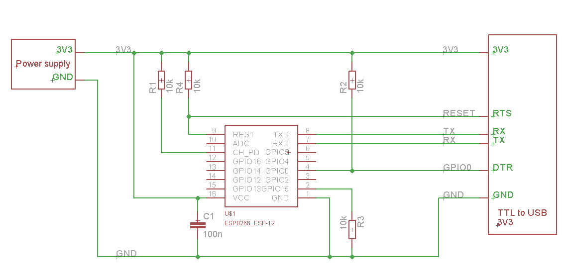
在其網頁下方的說明, 包含非常詳細的文件. 及 USB to serial + ESP8266 接法

ESP to Serial

Putting Device Into Flash Mode

To enable ESP8266 firmware flashing GPIO0 pin must be pulled low before the device is reset. Conversely, for a normal boot, GPIO0 must be pulled high or floating.
If you have a NodeMCU dev kit then you don't need to do anything, as the USB connection can pull GPIO0 low by asserting DTR and reset your board by asserting RTS.
If you have an ESP-01 or other device without built-in USB, you will need to enable flashing yourself by pulling GPIO0 low or pressing a "flash" switch, while powering up or resetting the module.

AT command 參考手冊 : 4a-esp8266_at_instruction_set_en from espressif


2016-09-07

Arduino 硬體規格

#原文規格說明
#最好也了解何謂 GPIO? PULLUP/PULLDOWN Resistor?

硬體規格:


微控制器 ATmega328
工作電壓 5V
輸入電壓(建議) 7-12V
輸入電壓(限制) 6-20V
數位 I/O Pins 14 支(其中有 6 支腳位可提供 PWM 輸出)
類入 Input Pins 6 支
I/O pin 直流電流 40mA
3.3V pin 直流電流 50mA
Flash 記憶體 32KB, 其中 0.5KB 拿去給 bootloader 使用
SRAM 2KB
EEPROM 1KB
時脈 16MHz

數位 I/O Pins:


14 支數位 I/O Pins 可以當作 input 使用,也可以當作 output 使用,使用方法是透過 pinMode(), digitalWrite(), and digitalRead() 這幾個函式。這 14 支數位 I/O Pins,其中幾支腳有特殊的功能:
Serial 通訊 0(RX) 和 1 (TX) 這兩支腳。用來接收(RX)與傳輸(TX) TTL 訊號的序列資料。這兩支腳也連接到 USB Converter 晶片中。
外部中斷 2 和 3 這兩支腳。這兩支腳可以利用外部事件觸發中斷。詳細內容請參考 attachInterrupt() 函式。
PWM 3, 5, 6, 9, 10 和 11 共六支腳。透過 analogWrite() 函式可以提供 8-bit 的 PWM 輸出。
SPI 10 (SS), 11 (MOSI), 12 (MISO) 和 13 (SCK) 這四支腳。這四支腳搭配 SPI Library 可提供 SPI 序列通訊。
LED 13。內建一顆 LED,當 pin 腳為 HIGH 時,LED 打開,當 pin 腳為 LOW 時,LED 關閉。

類比輸入 Pins:


Arduino Uno 有 6 支類比輸入腳,標記為 A0 到 A5,每支腳都可提供 10 位元的解析 (即 1024 種不同的數值)。這些腳位所用的參考電壓預設為 0 到 5V,不過參考電壓也是可以更改的,方法是透過 AREF 腳和 analogReference() 函式。 另外,有幾支腳也有特殊功能:
I2C 4 (SDA) 和 5 (SCL) 這兩支腳。透過 Wire library 可以提供 I2C 通訊。

其它:


AREF 類比輸入的參考電壓,搭配 analogReference() 函式一起使用。
Reset 當 Reset 腳為 LOW 時,微控制器會重置。