Reference : Converting an ATX Power Supply Into a DC Bench Supply
This article is the first in the “Projects” category. It’s a very inexpensive way to make a pretty good DC bench supply or dedicated 12 volt supply for working on projects or powering devices. As of this writing, a good quality and powerful ATX PSU (power supply unit) can be obtained online for about $20.00 or less. With the addition of a few inexpensive electronic parts (binding posts, LEDs, resistors, and some bits of hardware) a person with moderate electronic skills can do this project.
This article is the first in the “Projects” category. It’s a very inexpensive way to make a pretty good DC bench supply or dedicated 12 volt supply for working on projects or powering devices. As of this writing, a good quality and powerful ATX PSU (power supply unit) can be obtained online for about $20.00 or less. With the addition of a few inexpensive electronic parts (binding posts, LEDs, resistors, and some bits of hardware) a person with moderate electronic skills can do this project.
Below are links to some online articles and videos to use as examples done by other people. Most online references fall into two categories — converting an ATX PSU into a bench power supply or a dedicated 12 volt power supply.
Sometimes the instructions on the 12 volt conversions don’t include some of the finer points as the bench supply conversions. This article goes into more detail on some of the finer points:
- How to select the right dummy load resistor
- How to know where to install it
- How to heat sink it
- Plus a few more things
Online References
The following links are the online sources on how to convert a computer power supply into a DC bench supply:
WARNING!! – DO NOT ATTEMPT to modify a computer PSU unless you know what you are doing! There is a possible danger of electric shock WHICH CAN BE FATAL EVEN IF THE POWER SUPPLY IS NOT PLUGGED IN. When you open a power supply or attempt to modify it for purposes for which it was not intended, you do so at your own risk!
WATCH VIDEO
WikiHow: How to Convert a Computer ATX Power Supply to a Lab Power Supplyhttp://www.wikihow.com/Convert-a-Computer-ATX-Power-Supply-to-a-Lab-Power-Supply
Wikipedia reference on the ATX specification and its various revsions:http://en.wikipedia.org/wiki/Atx
Some Other Tools You Will Need
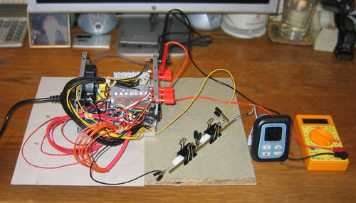
You will need a few extra tools to test for the right dummy load resistor by process of elimination. You will need a multimeter (to measure voltage, current and resistance), a thermometer, an assortment of power resistors and a cheap, 12 volt automotive 1157 tail lamp with some pieces of hookup wire soldered to it.
A. Multimeter – This is an inexpensive multimeter (under $10) that does everything you will need for this project.
B. Digital Thermometer – This is a digital meat thermometer, which can do the job for this project.
C. Dual Filament 12 volt Automotive Tail Light (#1157 bulb). Solder a yellow wire to the base contact for the dim (tail) light, a red wire to the base contact for the bright (brake) light and a black wire to the outside of the base (click picture above for larger view on where to solder the wires)
D. Assortment of Power Resistors – Please see the section below on testing the dummy load resistor.
What is an ATX Power Supply?
An ATX PSU (power supply unit) provides DC current for a computer in a number of voltages. It has a built in fan for cooling and delivers the various voltages to the computer via the power outputs. The wires in an ATX power supply are color-coded with different colored wires:
| Orange | +3.3v | Brown | +3.3v Sense |
| Red | +5v | Purple | +5v Standby |
| White | -5v (Older PSU) | Green | Power On |
| Yellow | +12v | Gray | Power Good |
| Blue | -12v | Black | GND |
There are a couple things to know about the color coded wires:
- Dell power supplies may use different color coded wiring, so be aware of this if you are planning to convert a Dell power supply.
- Older power supplies have a white wire for -5 volts and may not be present in newer PSUs.
- The brown +3.3v sense wire may not be present in some ATX PSUs and also may not be brown, exactly. If it is present, it must be joined with a +3.3v wire. If there is a +3.3v sense wire you will see it on the main power supply connector sharing one of the pins with an orange wire.
These are the important things to know about ATX color coded wires.
Wiring Diagrams
Please see the following wiring diagrams for converting an ATX power supply.
Wiring diagram for a DC bench supply:
Wiring diagram for a 12 volt power supply:
Whether you are building a DC bench supply or a 12 volt power supply you will need a dummy load resistor. The wiring diagrams above show a 10W, 10 Ohm dummy load resistor on the 5v rail installed between a black wire (GND) and a red wire (+5v). To install the dummy load resistor on the 12v rail, place it between a black wire (GND) and a yellow wire (+12v). Please see the sections below on the dummy load resistor and how to know which rail to install it.
Converting The Unit – Step by Step
Testing The Unit
1. First, before cutting any wires or dismantling the unit, test it to make sure it powers up. Using a short length of hookup wire, jump the pins between the green wire and any black wire in the main connector. Then plug in the power cord and throw the main power switch (if present) and see if the fan comes on. If so, you have power and you know the unit is good.
If the fan does not come one, try giving it a dummy load (please see the section below on why the PSU might need a dummy load). Using the 12 volt automotive 1157 lamp bulb with the wires soldered to it, insert the yellow wire into one of the yellow pins and the black wire into one of the black pins and then turn the switch back on. If the light bulb and fan comes on then you know the power supply is good. If it still does not come on then it is probably dead and you will have to get another one.
Cut and Organize the Wires
2. Remove the top of the case. This is usually done by removing 4 screws on the top panel.
3. Then cut all the connectors off the ends of the wires.
4. Next, organize all the wires according to color:
5. Group all the output wires:
- Orange (+3.3 volts)
- Red (+5 volts)
- White (-5 volts – on older PSUs, not present in later versions)
- Yellow (+12 volts)
- Blue (-12 volts)
- Black (ground)
6. Separate out the purple, gray green and brown wires:
- Purple (+5 volts standby)
- Gray (power good)
- Green (power on)
- Brown (+3.3 volts sense wire)
Case Layout
You will want to layout the positions of all the binding posts, switches and LEDs on your particular unit. You will have to work around the existing case layout. Typically, you will route the outputs to the back of the case where all the wires come out. You may also consider placing the binding posts for the outputs on the top of the case, especially if the PSU has a top-mounted fan. Some PSUs have a top-mounted fan and some have an internal fan. You just need to work around the available space and come up with a layout for the binding posts, LEDs and switches.
Typically, there are vent holes or slots in the existing PSU case for air flow. Mounting the binding posts requires that holes be drilled in the sheet metal case in the available spaces adjacent to these vent holes or slots. You have to plan carefully to avoid contact with internal electronic components or screws. Make sure to allow adequate clearance around the connections for all binding posts, switches or LEDs that you plan to add to the case.
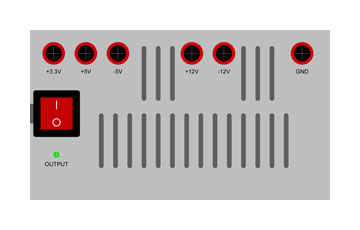
After you have worked out where to install all these additional components, it is helpful to prepare a template where to drill holes, make cuts or affix labels. Print out the template on plain paper, then cut it out and use glue tape or other adhesive to affix it to the case and use it as a guide for drilling holes or adding labels.
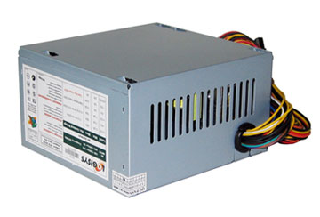
ATX power supply cases:
1. Coolmax V-400 or I-400 400W
For this case:
You can use this layout (download PDF layout template 1):
2. Logisys PS480D 480W
For this case:
You can use this layout (download PDF layout template 2):
12 volt power supply layout:
3. iMicro IM400W 400W
For this case:
You can use this layout (download PDF layout template 3):
A 12 volt power supply does not need to be as complicated as a bench supply. You only need 2 outputs (ground terminal plus 12 volt terminal). I decided to use a dual binding post with red and black terminals. This makes it easy for the user – no LEDs and no separate switch for the outputs. All the user has to do is connect the wires and turn on the main switch. That’s it.
The Big Hole on The Back of The Case
When deciding the best layout, your first question will be, “What do I do with that big hole on the back of the case?” (where all the wires come out).
When making a bench supply:
- Install a rocker switch in this big hole.
- If the PSU has no main power switch, then wire the rocker switch to power up the PSU. If this is the case, then Drill a 1/4 inch hole nearby and install a miniature toggle switch to power the outputs. This would be the switch that connects the green wire to the black wire to send power to the outputs.
- Otherwise, if the PSU does have a main power switch (like most modern ATX PSUs), then use the rocker switch to power the the outputs.
When making a 12 volt power supply:
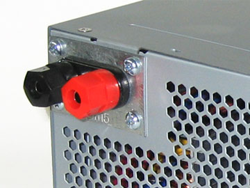
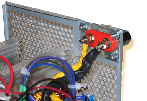
- Cut a metal plate to cover the outside of the hole and then drill 2 holes in this metal plate for a “dual binding post”.
- You can make a duplicate mating plate for the inside of the case and attach them both to the case with 4 machine screws and nuts through holes drilled in the corners of the plate.
- A 12 volt power supply won’t have a switch to power up the outputs. Simply connect the green wire to the black wire to power up the +12 volt output as soon as the main switch is turned on.
If you decide that you don’t want anything in that big hole and you just want to plug it up, then you can buy a “metal hole plug” from a local hardware supplier and simply plug it up. It can be secured to the inside of the case with hot glue so it won’t fall out or get loose.
Main Power Switch
Most PSUs sold today include a main power switch. Some older PSUs don’t have one so you may have to use the rocker switch as a main power switch (see previous section on what to do with the big hole in the back of the case). In this case you will cut the mains wires from where the mains power comes into the power supply and connect the cut wires to the rocker switch.
Miniature Toggle Switch
If you are building a DC bench supply and want to use the rocker switch as the main power switch, then drill a small 1/4 inch hole nearby and install a miniature toggle switch to use for the outputs. In this case you will connect the green wire and one black wire to the toggle switch. This is the only case where you would use a miniature toggle switch — when you are building a bench supply and the PSU does not come with a main power switch.
LEDs
Generally, if you want a bench supply with a red LED for main power (standby) and a green LED for the outputs, then you can:
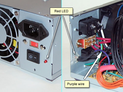
- Connect the purple wire (+5 volt standby) to the anode side of a red LED and one black wire with a load limiting resistor* to the cathode side of the red LED to indicate that mains power is supplied to the PSU (standby mode). Install the red (standby) LED near the main power switch.
- Connect the green wire and one black wire to a switch to turn on power to the outputs
- Connect the gray wire (power good) to the anode side of a green LED and one black wire with a load limiting resistor* to the cathode side of the green LED to indicate that power is supplied to the outputs. Install the green (output) LED near the output switch.
Secure the LEDs to the case by applying hot glue around the back side of each LED on the inside of the case (please refer to the photos above). Also please note in the photos above, the load limiting resistors for the LEDs are inside the heat shrink tubing on the black wires connecting to the LEDs.
*load limiting resistor (current limiting resistor): The wiring diagram calls for a 330 ohm resistor for the red LED and a 220 ohm resistor for the green LED. These should be good for most T-1, 3mm LEDs but the actual resistance required depends on the specifications of the LEDs themselves. The specifications for the proper load limiting resistor will sometimes be printed on the LED’s packaging. You can also use an online LED calculator to help choose the right resistors.
Connecting the Wires to the Binding Posts
If you are making a bench supply:
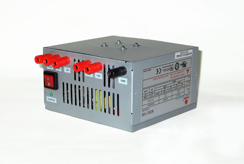
- You will want to install binding posts for each output voltage (+3.3v, +5v, -5v if present, +12v and -12v) plus one for the GND.
- Install binding posts for either on the back of the PSU case or on the top of the case – depending on the free space inside.
- You may also want to install a red LED near the main power switch to indicate that the PSU is powered up, plus
- You may want a second switch to turn on the outputs plus a green LED nearby to indicate that the outputs are powered up.
Use one black binding post for the GND and red binding posts for all of the output voltages. Connect all the colored wires for each output voltage to the various binding posts:
- Connect all the black wires (GND) to the binding post for the GND.
- Connect all the orange wires (+3.3v) plus the brown wire (+3.3v sense wire) to the +3.3v binding post.
- Connect all the red wires (+5v) to the +5v binding post.
- Connect the white wire (-5v, if present) to the -5v binding post.
- Connect all the yellow wires (+12v) to the +12v binding post.
- Connect the blue wire (-12v) to the -12v binding post.
Make sure to leave out some black wires and either one red wire or one yellow wire for the dummy load resistor.
- Leave one black wire for the red LED, a second black wire for the output switch plus the green LED and a third one for the dummy load resistor.
- Keep the remaining yellow wires twisted together, the remaining red wires twisted together and the remaining black wires twisted together, but unsoldered until after you complete the tests on the various dummy load resistors.
Note: Remember one more thing. When routing wires to the binding posts, don’t cut them too short. Allow enough length for the wires to be able to go AROUND the heat sink (refer to the photo below and please see the section below on how to heat sink the dummy load resistor). Usually all the colored wires for the outputs come from one side of the circuit board. You can usually route some of them to the binding posts on one side of the heat sink and some of them all the way around the back of the heat sink to the binding posts on the other side of it.
If you are making a 12 volt power supply:
- You will want to install only two binding posts – a red binding post for +12v and a black binding post for the GND.
- You can use a dual binding post for this purpose.
- You won’t need to install any LEDs or a separate switch to turn on the output.
Use one black binding post for the GND and one red binding post for the +12v output. Connect the following wires to the binding posts:
- Connect all the black wires (GND) to the binding post for the GND.
- Connect all the yellow wires (+12v) to the +12v binding post.
Make sure to leave out some black wires and either one red wire or one yellow wire for the dummy load resistor.
- Leave one black wire to be connected to the green wire (to power up the +12 volt output) and a second black wire for the dummy load resistor.
- Connect the green wire with one of the black wires. This will cause the outputs to power up.
- Then, simply cut the unused wires and either tape the ends off or cover them with heat shrink tubing. That would be the gray wire, the purple wire, the blue wire, the brown wire (if present) and white wire (if present) plus the orange wires and the remaining red wires.
- Keep the remaining yellow wires twisted together and the remaining black wires twisted together, but unsoldered until after you complete the tests on the various dummy load resistors.
Ring Terminals
Some of the outputs will have a lot of wires. Most of them are the black wires. There may be 12 or 13 black wires going to the GND binding post. Similarly, there may be 6 – 9 red wires going to the +5v binding post and 4 – 6 orange wires (plus a brown +3.3v sense wire) going to the +3.3v binding post and 6 – 7 yellow wires going to the +12v binding post.
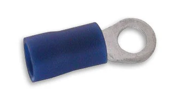
That’s a lot of wires going to a small binding post. To make it neat and serviceable, it is best to join all the wires to a to a #6 or #8 (16-14) ring terminal. The ring terminal fits squarely against the binding post nut and can be removed or replaced for servicing.
Twist the ends of the wires tightly, then solder them together. Cut off the vinyl sleeve from the ring terminal, then cut off the excess length of the soldered wires and then solder them (rather than crimp them) to the terminal. Pry open the crimp end of the ring terminal, if necessary, to fit all the twisted and soldered wires before soldering them to the terminal. After soldering the ring terminal, use heat shrink tubing to insulate it.
Just remember to keep the wires twisted together, but unsoldered until you have tested the dummy load resistor. Connect them temporarily to the binding posts with the twisted wire ends. Don’t put any solder on them until after the dummy load resistor tests, otherwise you won’t be able to wrap them around the binding post terminals.
Always Include a Dummy Load Resistor
One of the important things to do when converting an ATX power supply is to include a “dummy load” resistor. This is one of the things that is often omitted when building a 12 volt power supply that should always be included. A couple of questions come up when converting an ATX power supply regarding the dummy load resistor:
- How to make sure the dummy load resistor is the right power rating (in watts) and resistance (in ohms)
- How to tell whether to install it on the 5 volt rail or the 12 volt power rail
First, there are no hard and fast rules for specifying a dummy load resistor or which rail to put it on because power supplies vary a lot. Even the same model PSU from the same manufacturer may have variations from one unit to another. Second, it is not always clear which rail to install the dummy load resistor (either the 5 volt rail or the 12 volt rail). Rather than hard and fast rules, there are some general guidelines.
Why Do I Need a Dummy Load Resistor?
When you flip the switch that supplies AC current (mains power) to an ATX PSU it assumes it will be under load (by the presence of the mother board, computer processor and hard drives). The PSU fan will turn on and the outputs will supply power to the mother board, CPU, memory and hard drives. If you plug in an ATX power supply to AC current without connecting it to a computer, it may or may not power on. This is because an ATX PSU is a “switched mode” power supply which requires a load for it to function. In order to get the PSU to think it is connected to a computer, you have to connect a dummy load resistor to one of the power rails to fool it into thinking it is connected to a computer.
Some ATX PSUs will supply power to the outputs without a dummy load resistor. Even so, it may or may not be stable. Without a load, it may shut down. For this reason, it is best to provide a dummy load resistor to one of the power rails to ensure a stable, continuous supply of power to the different voltage outputs. The trick is to select the right dummy load resistor (with the right power rating and resistance) and to install it on the right power rail (either the 5 volt rail or the 12 volt rail).
Ceramic Power Resistors
I prefer to use inexpensive, ceramic cement wire wound power resistors for a dummy load because they are cheap, readily available and easy to install. A ceramic power resistor is also easy to install with a heat sink because they are rectangular and fairly uniform in size. Other, more expensive, power resistors are available with an aluminum shell with some built in heat sink functionality, but you can’t beat the price and availability of a ceramic wire wound resistor when selecting a dummy load resistor for your project. I keep a bunch of them on hand when setting up voltage and temperature tests. This way I can quickly determine the optimum dummy load resistor for my project without too much time and fuss. So far this has worked out very well for the ATX power supply conversions I have done.
Please don’t expect that this article will tell you to order a particular power resistor that will be optimum for a certain unit that you wish to convert because you will probably be disappointed. Rather, expect to have a number of power resistors onhand in your toolbox that you will use to test the PSU under load while measuring voltage and temperature in order to determine the best combination of resistance and wattage for your particular unit.
How to Heat Sink The Dummy Load Resistor
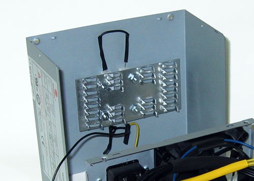
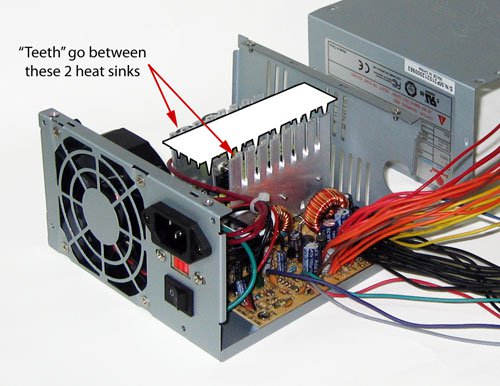
A dummy load resistor is expected to heat up. For this reason, it has to be rated with enough wattage to keep from failing plus it should always be heat sinked to dissipate the heat. The best way to heat sink a ceramic wire wound power resistor is to sandwich it between a flat metal plate and the inside top of the of the PSU case. Attach the heat sink with machine screws and nuts. Tighten the screws to clamp the ceramic power resistors between the metal case and the heat sink. A simple, cheap and effective heat sink can be used to secure the dummy load resistor to the power supply using an off the shelf hardware store item called a “mending plate”:
A mending plate is very inexpensive and adapts well as a heat sink. They come in convenient sizes (1″ x 4″ and 2″ x 4″) and are readily available in most hardware stores. The small 1″ x 4″ model (MP14) is perfect for one or two 5 watt ceramic power resistors:
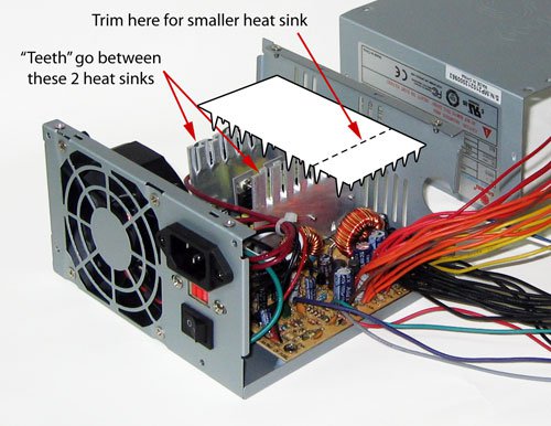
The 2″ x 4″ model (MP24) is good for one or two 10 watt ceramic power resistors. The 2″ x 4″ model should fit inside the PSU case. I used it full size on the 12 volt rail and then trimmed it down and used it in the same case on the 5 volt rail.
The ideal location to mount the resistors is in the path of the air flow between the vents at rear of the PSU case and the fan in the front. Many ATX PSUs have two large vertical heat sinks with a space between them. There is usually room to mount your dummy load resistor(s) on the inside of the case top between these two heat sinks. Be absolutely sure that your heat sink does not come into contact with the heat sinks mounted to the power supply circuit board, otherwise you can short out the unit.
The air space between them is open for air flow. The metal case itself plus the heat sink you install for the dummy load resistors provide the means to dissipate the heat generated by the dummy load resistors.
Testing Dummy Load Resistors
Q. How do I test the dummy load resistor to find the right one?
A. Test a number of them and check the output voltages and measure the temperature of the resistor(s) over a period of time (about 30 minutes on average). Select the power resistor(s) that generate the least amount of heat and provide output voltages with as little deviation from specification as possible. During the test you can connect a 12 volt automotive brake lamp to the ground and the +12 volt output and re-check the output voltage. This will give you an idea the voltage level when the unit is under load similar to real life conditions. The brake lamp provides a current load of about 1.9 amps.
You want to find the right dummy load resistor for your particular PSU. Power resistors of more or less resistance will cause the output voltages to vary. Variations in output voltage (in volts) as well as the current drawn by the resistor (in amps) will be affected by the resistance (in ohms). The more current drawn by the resistor (in amps) the more heat will be generated. You want to select a dummy load resistor with a high enough power rating (in watts) to give some headroom or a margin of safety.
You calculate the current and measure the watts for each resistor to make sure that the resistor will not burn out. As a rule of thumb, I like to have a margin of about 3 to 4 times the calculated wattage for a margin of safety. For example, if the calculated wattage on the resistor is 2.5 watts, then I would choose a 10 watt resistor. That would give me a resistor with 4 times the minimum wattage required (2.5 watts times 4 = 10 watts).
To determine the power (in watts) used by a resistor (in ohms):
Example: You want to test a 10W, 10 Ohm resistor on the 5 volt rail …
1. First, determine the current (in amps) on the resistor on a 5 volt line:
The current (in amps) is equal to the voltage (in volts) divided by the resistance (in ohms):
5v / 10 ohms = .5 amps
2. Then determine the power (in watts) on the resistor on a 5 volt line:
The the power (in watts) is equal to the voltage (in volts) times the current (in amps):
5v x .5 amps = 2.5 watts
Thus, a 10W, 10 Ohm resistor will handle 4 times the power required (10 watts is 4 times 2.5 watts).
Test a variety of resistors (different power ratings in watts and different resistances in ohms) and determine the best one or combination by process of elimination. Calculate the power requirement for the resistor in each case using the above formulas. Make sure that the power rating of the resistor is always more than the power requirement of the resistor on the particular rail you are checking (either the 5 volt rail or the 12 volt rail). I prefer a margin of safety or headroom of 3 to 4 times the power requirement for the resistor.
Below are some guidelines and starting points for testing the resistor(s):
1. For the 5 volt rail, start with a 10 Ohm resistor, then bracket it on either side (more and less) by 5 Ohms. That would be 5 Ohms and 15 Ohms. After checking these, narrow down the tests half way between these. That would be 7.5 Ohms and 12.5 Ohms.
2. For the 12 volt rail, check various 10W resistors between 20 Oms and 35 Ohms. Start in the middle somewhere – around 27.5 – 28 Ohms. Then try 35 Ohms and then 20 Ohms. Finally, check the in-between values – approximately 22.5 Ohms, 25 Ohms, 30 Ohms and then 32.5 Ohms. You get the idea.
You can connect two resistors in parallel or series to achieve the desired resistance (in ohms) and power rating (in watts). For example, to achieve the equivalent of a 10W, 10 Ohm resistor with two 5W resistors, you can connect two 5W, 20 Ohm resistors in parallel or two 10W, 5 Ohm resistors in series.
Twist the wires together on the binding posts and check the voltage of each output (+3.3v, +5v, -5v, +12v and -12v) plus the temperature of the resistor(s) every few minutes over time (about 30 minutes). Jot down the results. After a few tries with different combinations, you should notice a definite pattern. The goal is to have output voltages as close to specification as possible and the dummy load resistors as cool as possible. Resistors having different resistance (in ohms) will have an effect on the output voltage as well as the temperature of the power resistor(s). You should know the optimum combination of resistance and power rating for the dummy load resistor for you particular power supply within a short time.
Note: It is not always possible to obtain power resistors with the exact resistances you are looking for, so you may have to settle for values that are close, but not exact.
When testing the dummy load resistors you will want to make sure that all the wires of each color are twisted together at their respective outputs. Join all the orange wires (plus the brown +3.3 volt sense wire) for the 3.3 volt output, all the yellow wires for the +12 volt output, all the red wires for the +5 volt output and all the black wires for the ground. Keep the ends twisted, but not soldered until after you complete the tests on the dummy load resistors. Fewer wires will make a difference in the output voltages, so you want your tests to be accurate.
Determining Which Power Rail to Install The Dummy Load Resistor
Q. Which power rail do I install the dummy load resistor on?
A. As a general rule, you install the dummy load on either the +5 volt rail or the +12 volt rail, whichever one has the most power.
Check the specification placard on the side of the PSU case and check the power for each rail. The general guideline is to put the dummy load resistor on the rail with the most power. For example:
Example A and Example B above are both fairly straightforward. Most of the power is on the +5 volt rails so the dummy load resistor should be installed on the +5 volt rail in each example. Example C is a toss up. It is a newer power supply with dual 12 volt rails (+12V1 and +12V2). Although it is expected to install the dummy load resistor on the +12 volt rails, there is still quite a bit of power on the +3.3v and +5 volt rails. I tested this one both ways.
The dummy load resistor on the 12 volt rail was a little too hot for me even though the output voltages were good. I tested it also with the dummy load resistor on the 5 volt rail and it ran much cooler with hardly any difference in the output voltages. I decided to install two 10 watt, 15 ohm resistors in parallel for a the dummy load. This was equivalent to one 20 watt, 7.5 ohm resistor. It was a little overkill on the wattage, but using a resistor with a higher power rating is not harmful while using less could be.
Determining Whether to Use One Resistor or Two Resistors in Series or in Parallel
Q. Which is better for heat control – to use a single resistor or two resistors having the equivalent value when connected in series or in parallel?
A. When comparing power resistors of equivalent power rating (in watts) and resistance (in ohms), the smaller the overall mass, the less heat will be generated.
Examples – Using ceramic wire wound resistors:
5 watt resistor: width: 10 mm x height: 9 mm x length: 22 mm
10 watt resistor: width: 10 mm x height: 9 mm x length: 49 mm
Example D – One 10 watt, 10 ohm resistor generates about the same heat as two 5 watt, 20 ohm resistors in parallel because a 5 watt resistor is about half the mass of a 10 watt resistor and two of them will have about the same mass as a single 10 watt resistor.
Example E – Two 10 watt, 11 ohm resistors in series have twice the mass as a single 10 watt, 22 ohm resistor. In this example it is better and cooler to use a single resistor than two resistors in series.
The general rule is that two resistors in series will be hotter than a single resistor of equivalent value, whereas two resistors in parallel would be roughly the same as a single resistor of equivalent value and would make no difference in heat.













No comments:
Post a Comment
Note: Only a member of this blog may post a comment.