2017-11-15

AT-09 藍牙4.0BLE 模組 串口引出CC2541相容HM-10模組 連接單片機

重要參考文件

Data sheet
  • Type: Module of off-wire connection of Bluetooth
  • Microcontroller: TI CC2541
  • Size: 10cm x 6cm x 6cm
  • Communication modes: BLE
More information
  • AT+ command set on board
  • Customizable baud rate, device name, and pairing PIN
  • Automatically enters transparent serial mode after device is paired and connected
  • Returns to AT command mode when disconnected
  • Bluetooth version: V4.0
  • Default baud rate: 9600
  • Default serial port setting: 9600, N, 8, 1
  • Voltage: 3.3V
  • VCC:  input power supply 3.3~6V, Prohibit more than 7V
  • GND: Ground
  • TX:  transport
  • RX:  receive  
  • State: when bluetooth is connected , output "High level", "no conntected"  output "low level"
  • EN:when module is connected, give a high level to "EN", the module will disconnected.

2017-11-06

Arduino nano 安裝 Arduino uno 的 bootloader

方法 : How to Burn a Bootloader to Clone Arduino Nano 3.0
1. 單獨將 Arduino uno 連到電腦, 上傳 ArduinoISP 到 Arduino uno
2. 拆下 Arduino uno, 連接 Arduino uno 與 Arduino nano
3. 連接 Arduino uno 與電腦, Arduino IDE-Tools-Programmer 設為 "Arduino as ISP", 接著執行 "Burn Bootloader"

困難 : Arduino nano 安裝 Arduino uno bootloader 之後一直無法上傳程式. 後來改用 portable Arduino IDE version version 1.8.5, 重新執行一次上述方法後就成功了. (真正原因為何?)

記得 : 之後使用此 Arduino nano, Arduino IDE-Board 必須選取 "Arduino/Genuino Uno". 因為它已安裝了 Arduino uno bootloader.

好處 : Arduino uno bootloader 體積較小, 部屬程式較快

2017-10-10

ESP8266 機智雲開發板 ESP-12F Wifi模組 ESP-12E 增強版

參考論壇


  • 上板按鈕接到  <GPIO4> 接腳
  • RGB LED 控制分別接到 <GPIO15> 、<GPIO12> 和 <GPIO13> 接腳
  • CDS ( 光敏電阻 ) 的輸入訊號接到上板的 ADC 接腳
  • 不管 MicroUSB 埠使用上板的或是下板的,電壓只能使用 USB 供電範圍的電壓,也就是 DC 5V,不然就有可能燒壞下板晶片!

2017-10-06

使用 NodeMCU

Tools to flash nodemcu-lua or micropython firmware

1. ESP8266 Flasher (參考 ESP8266: Reflash Dance!)
2. Nodemcu Flasher
3. Flash download tools
4. esptool : command mode
5. NodeMCU pyflasher : Self-contained NodeMCU flasher with GUI based on esptool.py and wxPython

注意 SPI MODE 的選取 : flash memory >= 4MB 時點選 DIO, others : QIO
Reference 1. NodeMCU docs

To enable ESP8266 firmware flashing GPIO0 pin must be pulled low before the device is reset. Conversely, for a normal boot, GPIO0 must be pulled high or floating.
If you have a NodeMCU dev kit then you don't need to do anything, as the USB connection can pull GPIO0 low by asserting DTR and reset your board by asserting RTS.
If you have an ESP-01 or other device without built-in USB, you will need to enable flashing yourself by pulling GPIO0 low or pressing a "flash" switch, while powering up or resetting the module.

2017-08-16

直流數字雙顯電壓電流表 數顯表頭 12V 10A 0-100V電壓電流檢測

產品特點:
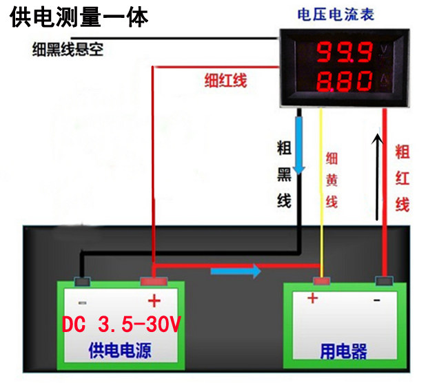
     功能完善集電壓電流表於一身,測量電流時電源取自測量線路,不需要隔離的電源進行單獨供電,使用方便。

注意:本款電流只可測負極單向電流,沒法同時測充電和放電,如需測量雙向的,有可測正極和負極線路的雙顯表,可以點擊圖片,拍下面那塊。
參數如下:
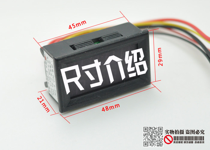
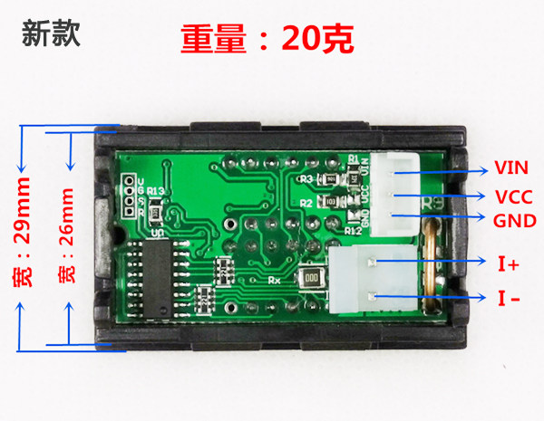
開口尺寸:45mm*26mm(開口直接將表卡入面板)
外形尺寸:48mm*29mm*21mm
供電電壓: DC3.5-30V (細紅線正極, 細黑線負極) 切記供電線不可過壓
重 量:20克/只
顯示方式:雙3位0.28寸LED數碼管
顯示顏色:紅色+紅色/ 紅色+綠色
刷新速度:約500ms/次
測量精度:±(1%+2個字)
電壓表量程:DC 0-100V (分辨率0.1V)
電流表量程:DC 0-9.99A(分辨率0.01A)
  
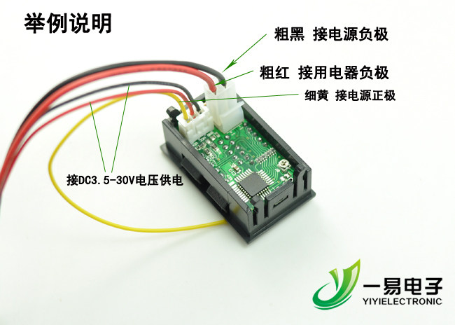
板載電線功能說明:
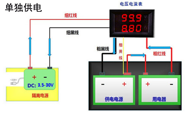
細紅線(VCC) :供電電源輸入正極(3.5-30V)注意:如果測量信號低於30V, 且供電充足. 可以直接作為模塊的供電電源(將細黃線和細紅線並聯使用)
細黑線(GND) :供電電源輸入負極(3.5-30V)與測量信號共地
細黃線(VIN) : 測量信號輸入正極(0-100V)
粗紅線(I+) : 電流輸入正極(必須接在負載負極)
粗黑線(I-) :電流輸入負極(必須串聯在供電負極)
接線使用提醒:表頭只能測量負極線路電流,即把粗黑線和粗紅線串聯至被測電路的負極線路上即可,並注意粗黑線和粗紅線的位置,只能測單向電流,接反沒法顯示電流,如串聯到了正極會導致表頭損壞。
詳細接線圖如下:

  
 舉例說明
 
誤差現象:
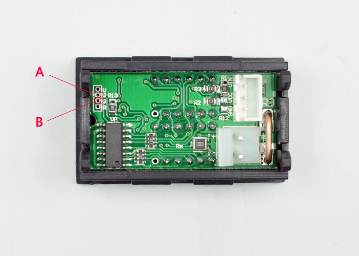
1、由於器件老化/環境溫度影響模塊測量小電流時誤差變大
解決辦法:空載時短路A 和B 個焊盤然後通電開機,模塊會自動校準零點,校準完成後關機斷開短路點。

2017-05-23

更新 ESP8266 ESP-01 firmware 的方法

1. 燒錄前要將 GPIO0 接地才行 (須在 power up 之前, 因 ESP8266 是在電源打開時偵測 GPIO 以便決定是否進入燒錄模式), 燒錄完成後再拔掉GPIO0接地線 :


2. follow : ESP8266 WiFi module firmware update ( 若無法立即執行, 按一下 power reset 即可 )

3. Firmware download tool : 注意 SPI MODE 的選取, flash memory >= 4MB : DIO, others QIO

2017-05-20

udev

來源 :
1. udev-強大的device node管理系統
2. Howto--udev rules

一、devfs

linux下有專門的檔系統用來對設備進行管理,devfs和sysfs就是其中兩種。

在2.6內核以前一直使用的是devfs,devfs掛載於/dev目錄下,提供了一種類似於檔案的方法來管理位於/dev目錄下的所有設備,我們知道/dev目錄下的每一個檔案都對應的是一個設備,至於當前該設備存在與否先且不論,而且這些特殊檔是位於根檔系統上的,在製作檔案系統的時候我們就已經建立了這些設備檔,因此通過操作這些特殊檔,可以實現與內核進行交互。但是devfs檔案系統有一些缺點,例如:不確定的設備映射,有時一個設備映射的設備檔可能不同,例如我的U盤可能對應sda有可能對應sdb;沒有足夠的主/輔設備號,當設備過多的時候,顯然這會成為一個問題;/dev目錄下檔太多而且不能表示當前系統上的實際設備;命名不夠靈活,不能任意指定等等。

udev的出現, 解決了在devfs上碰到的3個問題
1.udev能夠根據規則建立device node(這可以解決probing時,device node可能會依probing的順序不同而改變)
2.udev動態建立device node,不會像以前在/dev資料夾下擺一堆多而無用的device node
3.提供user更方便的API存取目前device的資訊,在kernel 2.6以上已提供sysfs這個device管理機制

二、sysfs

正因為上述這些問題的存在,在linux2.6內核以後,引入了一個新的檔案系統sysfs,它掛載於/sys目錄下,跟devfs一樣它也是一個虛擬檔案系統,也是用來對系統的設備進行管理的,它把實際連接到系統上的設備和匯流排組織成一個分階層的檔案目錄,用戶空間的程式同樣可以利用這些資訊以實現和內核的交互,該檔案系統是當前系統上實際設備樹的一個直觀反應,它是通過kobject子系統來建立這個資訊的,當一個kobject被創建的時候,對應的檔案和目錄也就被創建了,位於/sys下的相關目錄下,既然每個設備在sysfs中都有唯一對應的目錄,那麼也就可以被用戶空間讀寫了。用戶空間的工具udev就是利用了sysfs提供的資訊來實現所有devfs的功能的,但不同的是,udev運行在用戶空間中,而devfs卻運行在內核空間,而且udev不存在devfs那些先天的缺陷。很顯然,sysfs將是未來發展的方向。

The top level sysfs directory looks like:
block/
bus/
class/
devices/
firmware/
net/
fs/

devices/ contains a filesystem representation of the device tree. It maps directly to the internal kernel device tree, which is a hierarchy of struct device.

bus/ contains flat directory layout of the various bus types in the kernel. Each bus's directory contains two subdirectories:
       devices/
       drivers/
devices/ contains symlinks for each device discovered in the system that point to the device's  directory under root/.

drivers/ contains a directory for each device driver that is loaded for devices on that particular bus (this assumes that drivers do not span multiple bus types).

fs/ contains a directory for some filesystems. Currently each filesystem wanting to export attributes must create its own hierarchy below fs/ (see ./fuse.txt for an example).

三、udev

udev是一種工具,它能夠根據系統中的硬體設備的狀況動態更新設備檔,包括設備檔的創建,刪除等。設備檔通常放在/dev目錄下,使用udev後,在/dev下面只包含系統中真實存在的設備。它於硬體平臺無關的,位於用戶空間,需要內核sysfs和tmpfs的支援,sysfs為udev提供設備入口和uevent通道,tmpfs為udev設備檔提供存放空間。

udev運作的原理很簡單,它透過netlink得知目前kernel有那些module新增了,在收到kernel module新增的netlink訊息之後,它會先掃描user是否有指派device node rule,如果沒有,會自動根據module的major和minor number建立device node.有一點比較特殊的地方是,udev用inotify監聽rule變化的event,所以可以即時改變device node的狀態,udev的架構圖可參考如下


如前述,udev的功能是動態的對/dev/下的device node做增減的動作。動態增減是為了解決以往/dev下有太多沒用到的device node,而devfs又有一些"先天的缺陷":

1. 屬於kernel space
2. 存在一些可解和解不了的bug
3. 作者消失,維護者也不見了
4....

在種種原因下,udev取代了devfs。當然 devfs也不是沒有優點,如比較小,比較快(速度),比較省(memory),但anyway,過去就讓它過去了。


來吧
基本上,rule是用來在某些條件成立後,執行指令,包括增減device node,並執行外部程式等。比如說,在插入usb disk時,建立/dev/sdb,並mount起來,然後彈出檔案總管。大致條列如下:
1. 將kernel預設的device node改個名字,如把/dev/sdb改成 /dev/apacer-8G (by NAME, no longer works after udev became a part of systemd ??? )
2. 為預設device node建立symbolic link (by SYMLINK)
3. 更彈性的用法,用外部程式來替device node命名 (by PROGRAM)
4. 改變device node的permission和ownership (by GROUP and MODE)
5. device node增減時,執行shell script (by RUN)

時機
通常改變rule是為了改變系統預設的行為,因此,會希望在預設動作前,先完成自己想要做的事。而udev是根據字母排序來parse rule。在rule裡,#開頭的是註解,且每條rule都要在同一行,每條非空行都被視為一條rule。同一個device可以match多條rule,udev會apply每條match的rule。

Syntax
每條rule是由一串(key, value)組成,由comma(“,”)區隔。兩種key:
1. match key(==): 用來識別device,並決定是否要執行該條rule
2. assignment key(=): 當所有的match key都成立,則執行assignment key指定的指令。
每條rule至少要有一個match key和assignment key。
比如說:
        KERNEL==”sdb”, NAME=”usb_disk”
意思是如果kernel report sdb這個device,則建立usb_disk這個device node (就不會有sdb這個node了)。不過這是比較沒鑑別的rule,因為sdb會隨著插入的順序而assign給不同的usb disk,因此最好是使用可uniquely identified的match key,見下述。
常用的match key如下:
KERNEL: kernel所給的預設名字 (如,sda, lp等)
SUBSYSTEM: device所屬的subsystem,如net, block, usb (可由sysfs得知)
DRIVER: 該device所使用的driver
常用的assignment key如下:
NAME: 該device node的名字
SYMLINK: device node的另一個名字,用symbolic link。這個link可以有很多個,所以可以用+=來做assignmet。
PROGRAM: 指定所需執行的外部程式,其stdout可用來指定device node的名字,用%c表示。若不止一個output,也可用%c{1},%c{2}或%c{2+}等表示式。
RUN: 在某些rule成立時,再多執行另一個外部程式。這和PROGRAM有點像,只是PROGRAM是用來產生device node的名字。

正規表示法
match key也有類似正規表示法的東西:
*:match任一個字母,0個或多個
?:match一個字母
[]: match 括號內任一個字母,可以是某個range,如[a-p],[0-9],或是[!1-3]
例如:
KERNEL=”sd*| hd[a-e]”, NAEM=”block/%k”

字串代換
類似printf的表示法:
%k: kernel給的預設名字,如sdb1
%n:kernel給的device number,若%k是sdb1,則%n是1
%c:外部程式的stdout
特殊字元%與$若要拿來當match key,需寫為:%%和$$

Sysfs登場
以上都是解釋,接下來就是真正的應用了。每個device插入系統時,會export一大堆訊息給sysfs,因此在sysfs裡有許多可用的訊息,而且是可以在rule裡直接剪下貼上的,因此udev和sysfs的關係是相當的密切。先從sysfs裡看看有什麼可以挖的吧!
使用udevinfo來query sysfs:
先插入一個usb disk,看看kernel給了什麼預設的名字:
user@user-ubuntu:/etc/udev/rules.d$ cat /proc/partitions
major minor #blocks name
8 0 244198584 sda
8 1 78180291 sda1
8 2 1 sda2
8 5 158200056 sda5
8 6 7815591 sda6
7 0 10240000 loop0
8 16 7823360 sdb
8 17 7819328 sdb1
這樣可知道,是在sdb,而真正要mount的是sdb1,來查一下:
udevadm info -a -p /sys/block/sdb/sdb1 會看到如下的output (只挑其中兩段做例子):
looking at device '/devices/pci0000:00/0000:00:1d.7/usb4/4-3/4-3:1.0/….':
KERNEL=="sdb1"
SUBSYSTEM=="block"
DRIVER==""
ATTR{start}=="8064"
ATTR{size}=="15638656"
ATTR{stat}==" 78 2219 2765 164 4 ……."

looking at parent device '/devices/pci0000:00/0000:00:1d.7/usb4/4-3/4-3:1.0/…':
KERNELS=="52:0:0:0"
SUBSYSTEMS=="scsi"
DRIVERS=="sd"
ATTRS{device_blocked}=="0"
ATTRS{type}=="0"
ATTRS{scsi_level}=="0"
ATTRS{vendor}==" "
ATTRS{model}=="USB FLASH DRIVE "
ATTRS{rev}=="PMAP"
ATTRS{state}=="running"
ATTRS{timeout}=="30"
ATTRS{iocounterbits}=="32"
ATTRS{iorequest_cnt}=="0xe3"
ATTRS{iodone_cnt}=="0xe3"

其實這些資訊都是透過driver export給sysfs,而udevinfo只是透過sysfs裡所記錄的內容,整理過後程現出來有關這個device的屬性。而這些屬性都是可以用來做match key。還有一個原則是每段的屬性是不能交互寫在同一個rule。比如說:
KERNEL==”sdb1”, ATTR{size}=="15638656", NAME=”apacer-disk”
SUBSYSTEMS=="scsi", ATTRS{model}=="USB FLASH DRIVE ", NAME=”apacer-disk”
這兩條rule都是對的,但不能這樣用:
KERNEL==”sdb1”, ATTR{size}=="15638656", ATTRS{model}=="USB FLASH DRIVE ", NAME=”apacer-disk”

Permission and ownership
這個比較直覺,就是設定而已
KERNEL==”sdb1”, ATTR{size}=="15638656", NAME=”apacer-disk”, GROUP=”user”, MODE=”0755”
結果如下:
brwxr-xr-x 1 root user 8, 33 2009-07-03 21:52 apacer-8g

Naming by External Program
比較複雜的情況下,可以存在一支命名程式,使用其stdout來當作device node的名字。在rule中,甚至可以傳參數給這支外部程式。其stdout用%c來表;
示,若有多組output,可用%c{1},%c{2}或%c{2+}這樣的表示方式。舉例如下

SUBSYSTEM=="block", ATTR{size}=="15638656", PROGRAM=”/usr/bin/usb-naming %k”, NAME=”%c”
%k是kernel預設的名字,usb-naming接收此名字後,output結果至stdout。

Run external program upon events
當收到某個udev event後,可再執行某個外部指令。這個跟PROGRAM類似,但不是做naming。比如說,在mount完usb後,做個記錄,可以這麼寫:
SUBSYSTEM=="block", ATTR{size}=="15638656", NAME=”apacer-8g”, RUN+=”/usr/bin/mount-log %k”。

特殊選項
all_partition: 意思大概是為block device建立所有可能的partition,而不是只建一開始偵測到的,不知道這個有什麼應用。
ignore_device:忽略這個event。這個還蠻好用。有些usb有不止一個partition,比如說一個是開機,一個是data。如果每次udev都把這兩個 partition mount起來,但是開機 那個永遠用不到,那就很煩。可用這個選項來忽略開機partition的event。比如:
SUBSYSTEM=="block", ATTR{size}=="1440", OPTIONS+=”ignore_device”
last_rule:對該device不再match之後的rule

2017-04-18

bootstrap of Allwinner A64

source :
1. [u-boot.git] / board / sunxi / README.pine64
2. Allwinner 64-bit boards README

   1 Pine64 board README
   2 ====================
   3
   4 The Pine64(+) is a single board computer equipped with an AArch64 capable ARMv8
   5 compliant Allwinner A64 SoC.
   6 This chip has ARM Cortex A-53 cores and thus can run both in AArch32
   7 (compatible to 32-bit ARMv7) and AArch64 modes. Upon reset the SoC starts
   8 in AArch32 mode and executes 32-bit code from the Boot ROM (BROM).
   9 This has some implications on U-Boot.
  10
  11 Quick start
  12 ============
  13 - Get hold of a boot0.img file (see below for more details).
  14 - Get the boot0img tool source from the tools directory in [1] and compile
  15   that on your host.
  16 - Build U-Boot:
$ git clone https://github.com/u-boot/u-boot.git
$ cd u-boot
$ export CROSS_COMPILE=aarch64-linux-gun-
$ make pine64_plus_defconfig
$ make
  17 $ export CROSS_COMPILE=aarch64-linux-gnu-
  18 $ make pine64_plus_defconfig
  19 $ make
  20 - You also need a compiled ARM Trusted Firmware (ATF) binary. Checkout the
  21   "allwinner" branch from the github repository [2] and build it:
$ git clone https://github.com/apritzel/arm-trusted-firmware.git
$ cd arm-trusted-firmware
$ git checkout allwinner
$ export CROSS_COMPILE=aarch64-linux-gnu-
$ make PLAT=sun50iw1p1 DEBUG=1 bl31
  22 $ export CROSS_COMPILE=aarch64-linux-gnu-
  23 $ make PLAT=sun50iw1p1 DEBUG=1 bl31
  24   The resulting binary is build/sun50iw1p1/debug/bl31.bin.
  25
  26 Now put an empty (or disposable) micro SD card in your card reader and learn
  27 its device file name, replacing /dev/sd below with the result (that could
  28 be /dev/mmcblk as well):
  29
  30 $ ./boot0img --device /dev/sd -e -u u-boot.bin -B boot0.img \
  31         -d trampoline64:0x44000 -s bl31.bin -a 0x44008 -p 100
  32 (either copying the respective files to the working directory or specifying
  33 the paths directly)
  34
  35 This will create a new partition table (with a 100 MB FAT boot partition),
  36 copies boot0.img, ATF and U-Boot to the proper locations on the SD card and
  37 will fill in the magic Allwinner header to be recognized by boot0.
  38 Prefix the above call with "sudo" if you don't have write access to the
  39 uSD card. You can also use "-o output.img" instead of "--device /dev/sd"
  40 to create an image file and "dd" that to the uSD card.
  41 Omitting the "-p" option will skip the partition table.
  42
  43 Now put this uSD card in the board and power it on. You should be greeted by
  44 the U-Boot prompt.
  45
  46
  47 Main U-Boot
  48 ============
  49 The main U-Boot proper is a real 64-bit ARMv8 port and runs entirely in the
  50 64-bit AArch64 mode. It can load any AArch64 code, EFI applications or arm64
  51 Linux kernel images (often named "Image") using the booti command.
  52 Launching 32-bit code and kernels is technically possible, though not without
  53 drawbacks (or hacks to avoid them) and currently not implemented.
  54
  55 SPL support
  56 ============
  57 The main task of the SPL support is to bring up the DRAM controller and make
  58 DRAM actually accessible. At the moment there is no documentation or source
  59 code available which would do this.
  60 There are currently two ways to overcome this situation: using a tainted 32-bit
  61 SPL (involving some hacks and resulting in a non-redistributable binary, thus
  62 not described here) or using the Allwinner boot0 blob.
  63
  64 boot0 method
  65 -------------
  66 boot0 is Allwiner's secondary program loader and it can be used as some kind
  67 of SPL replacement to get U-Boot up and running.
  68 The binary is a 32 KByte blob and contained on every Pine64 image distributed
  69 so far. It can be easily extracted from a micro SD card or an image file:
  70 # dd if=/dev/sd of=boot0.bin bs=8k skip=1 count=4
  71 where /dev/sd is the device name of the uSD card or the name of the image
  72 file. Apparently Allwinner allows re-distribution of this proprietary code
  73 as-is.
  74 For the time being this boot0 blob is the only redistributable way of making
  75 U-Boot work on the Pine64. Beside loading the various parts of the (original)
  76 firmware it also switches the core into AArch64 mode.
  77 The original boot0 code looks for U-Boot at a certain place on an uSD card
  78 (at 19096 KB), also it expects a header with magic bytes and a checksum.
  79 There is a tool called boot0img[1] which takes a boot0.bin image and a compiled
  80 U-Boot binary (plus other binaries) and will populate that header accordingly.
  81 To make space for the magic header, the pine64_plus_defconfig will make sure
  82 there is sufficient space at the beginning of the U-Boot binary.
  83 boot0img will also take care of putting the different binaries at the right
  84 places on the uSD card and works around unused, but mandatory parts by using
  85 trampoline code. See the output of "boot0img -h" for more information.
  86 boot0img can also patch boot0 to avoid loading U-Boot from 19MB, instead
  87 fetching it from just behind the boot0 binary (-B option).
  88
  89 FEL boot
  90 =========
  91 FEL is the name of the Allwinner defined USB boot protocol built-in the
  92 mask ROM of most Allwinner SoCs. It allows to bootstrap a board solely
  93 by using the USB-OTG interface and a host port on another computer.
  94 Since FEL boot does not work with boot0, it requires the libdram hack, which
  95 is not described here.
  96
  97 [1] https://github.com/apritzel/pine64/
  98 [2] https://github.com/apritzel/arm-trusted-firmware.git

2017-04-16

Linux - how to format multiple file systems within one file?

source : Linux - how to format multiple file systems within one file?

psihodelia:

Linux - how to format multiple file systems within one file?
I need to create a disk image with two empty file systems. I have created it using

dd if=/dev/zero of=./disk.img bs=1MiB count=1024

Next, I have created 2 primary partitions using fdisk disk.img; one is FAT32 and other is EXT3. Now, I have to format both partitions in order to create file-systems to be mounted as -o loop devices. But I can't understand how to format them? I can't use mkfs.vfat on disk.img. So I am totally confused.
SOLUTION: Thanks to answer from @pjc50 I found very simple solution:

sudo aptitude install multipath-tools
sudo kpartx -a disk.img   #it maps (mounts) found partitions to /dev/mapper/loop...
sudo mkfs.vfat -F 32 -n boot /dev/mapper/loop0p1
sudo mkfs.ext3 -L rootfs /dev/mapper/loop0p2

A drawback of this solution is requirement of superuser rights.

-----------------------------------------------------------------------
karatedog:
I would go with the tools I have in mind:
create a new VM in Virtualbox with one disk, that would usually be /dev/sda
boot into the VM with a GParted Live CD
partition and format the disk in the VM to your needs (2 partitions, different file systems, etc.)
then use dd to export /dev/sda to a file
With an educated guess it would take about 15 minutes.

-----------------------------------------------------------------------
Shawn Chin:
You can do so by first mounting your partitions to /dev/loop? using losetup with the -o option to specify a suitable offset to your partition. The offset can be calculated based on the output of fdisk -l disk.img (start_sector * sector_size).
For example:

losetup -o32256 /dev/loop1 ./disk.img   # mount first partition

Once mounted, you can then proceed to format the partition using mkfs.*:

mkfs.vfat -F32 /dev/loop1

For more details and examples, see the following articles:
http://wiki.osdev.org/Loopback_Device#Mounting
http://web2.clarkson.edu/projects/itl/honeypot/ddtutorial.txt
http://wiki.eeeuser.com/howtocustomrestoreimage:pt2mkcustomimage

-----------------------------------------------------------------------
pjc50
It appears you can use the kpartx tools: http://robert.penz.name/73/kpartx-a-tool-for-mounting-partitions-within-an-image-file/
Kpartx can be used to set up device mappings for the partitions of any partitioned block device. It is part of the Linux multipath-tools. With kpartx -l imagefile you get an overview of the partitions in the image file and with kpartx -a imagefile the partitions will accessible via /dev/mapper/loop0pX (X is the number of the partition). You can mount it now with mount /dev/mapper/loop0pX /mnt/ -o loop,ro. After unmounting you can disconnect the mapper devices with kpartx -d imagefile.

2017-03-06

安裝 ARM ToolChain on Debian

in Synaptic, install

1. crossbuild-essential-arm64 : 64 bits
2. crossbuild-essential-armel : 32 bits, soft floating point
3. crossbuild-essential-armhf : 32 bits, hard floating

為了方便未來我們使用, 三個不同版本的工具,可在 ~/.bashrc 中新增底下設定:

alias makearmel='make ARCH=arm CROSS_COMPILE=arm-linux-gnueabi-'
alias makearmhf='make ARCH=arm CROSS_COMPILE=arm-linux-gnueabihf-'
alias makearm64='make ARCH=arm64 CROSS_COMPILE=aarch64-linux-gnu-'

----------------------------------------------------------------------------------------------
以 qemu-arm 測試:

: arm-linux-gnueabihf-gcc hello.c -o hello_arm
: qemu-arm -L /usr/arm-linux-armhf hello_arm

*** 善用 man qemu-arm ***

Kernel Building for Raspberry pi (ARM CPU)

1. [進階] 安裝 Raspberry Pi 的 Toolchain
2. [進階] 編譯 Raspberry Pi 的核心 OR KERNEL BUILDING : DOCUMENTATION > LINUX > KERNEL > BUILDING

raspberrypi-tools 是 32bits 的,所以在 debian wheezy amd64 要裝上 32bits 的程式庫。
$ sudo apt-get install libc6-i386 lib32stdc++6 lib32z1

裝好後,試試看指令能不能執行
$ arm-linux-gnueabihf-gcc
arm-linux-gnueabihf-gcc: fatal error: no input files
compilation terminated.

這樣 no input files 就是正常可執行的狀況

-bash: /opt/cross/arm-bcm2708/gcc-linaro-arm-linux-gnueabihf-raspbian/bin/arm-linux-gnueabihf-gcc: No such file or directory

若出現 No such file or directory 則應該是 32bits 程式庫沒裝好,再用 ldd 檢查一下。

armel和armhf區別選擇


出於低功耗、封裝限制等種種原因,之前的一些ARM架構處理器因為內部資源寶貴,加入浮點運算單元是十分奢侈的,因為需要額外的軟件實現。隨著技術發展,目前高端的ARM處理器已經具備了硬件執行浮點操作的能力。這樣新舊兩種架構之間的差異,就產生了兩個不同的嵌入式應用程序二進制接口(EABI)——軟浮點與矢量浮點(VFP)。但是軟浮點(soft float)和硬浮點(hard float)之間有向前兼容卻沒有向後兼容的能力,也就是軟浮點的二進制接口(EABI)仍然可以用於當前的高端ARM處理器

fpu單元

在ARM體系架構內核中,有些有浮點運算單元(fpu),有些沒有。對於沒有fpu內核,是不能使用armel和armhf的。在有fpu的情況下,就可以通過gcc的選項-mfloat-abi來指定使用哪種,有如下三種值:
  • soft:不用​fpu計算,即使有fpu浮點運算單元也不用。
  • armel:也即softfp,用fpu計算,但是傳參數用普通寄存器傳,這樣中斷的時候,只需要保存普通寄存器,中斷負荷小,但是參數需要轉換成浮點的再計算。
  • armhf:也即hard,用fpu計算,傳參數用fpu中的浮點寄存器傳,省去了轉換性能最好,但是中斷負荷高。
kernel、rootfs和app編譯的時候,指定的必須保持一致才行。
使用softfp模式,會存在不必要的浮點到整數、整數到浮點的轉換。而使用hard模式,在每次浮點相關函數調用時,平均能節省20個CPU週期。對ARM這樣每個週期都很重要的體系結構來說,這樣的提升無疑是巨大的。
在完全不改變源碼和配置的情況下,在一些應用程序上,雖然armhf比armel硬件要求(確切的是指fpu硬件)高一點,但是armhf能得到20-25%的性能提升。對一些嚴重依賴於浮點運算的程序,更是可以達到300%的性能提升。

armel與armhf

之前EABI中,armel(低端ARM硬件,支持armv4以上版本),在執行浮點運算之前,浮點參數必須首先通過整數寄存器,然後傳遞到浮點運算單元。新的EABI ,也就是armhf,通過直接傳遞參數到浮點寄存器優化了浮點運算的調用約定。
相比我們熟悉的armel,armhf代表了另一種不兼容的二進制標準。在一些社區的支持下,armhf目前已經得到了很大的發展。像Ubuntu,已經計畫在之後的發行版中放棄armel,轉而支持armhf編譯的版本。正如目前依然很火熱的Raspberry Pi(ARM11),由於ubuntu只支持armv7架構的編譯,Raspberry Pi將不能直接安裝ubuntu系統。而BB Black(Cortex-A8)和Cubietruct(Cortex-A7)則同時支持ubuntu的armel與armhf的編譯。

安裝armel和armhf

以上就是armel與armhf的比較。相信大家也應該有個大概的瞭解了。在Ubuntu系統下,如何根據需求分別實現兩種交叉編譯器的安裝呢?

arm-linux-gnueabi的安裝 (debian synaptic supported)

sudo apt-get install gcc-arm-linux-gnueabi
按操作下載即可,沒啥好說的。

 arm-linux-gnueabihf的安裝 (debian synaptic supported)

兩種方法,
  1. linaro開源組織有相關的交叉工具鏈下載,點擊進入網頁選擇下載即可,地址:https://launchpad.net/linaro-toolchain-binaries
  2. 到本站工具鏈頁面下載,地址:http://www.veryarm.com/arm-linux-gnueabihf-gcc
然後就是解壓到自定義目錄中,並添加bin環境變量。

armhf 使用

armhf的開啟需要硬件的支持,在Debian的wiki上要求ARMv7 CPU、Thumb-2指令集以及VFP3D16浮點處理器。
在gcc的編譯參數上,使用-mfloat-abi=hard -mfpu=vfp即可。
在工具上,CodeSourcery最早支持hard模式。或者,也可已自己編譯工具鏈。

2017-02-25

WHR-G300N v1 Boot Log

=~=~=~=~=~=~=~=~=~=~=~= PuTTY log 2017.02.24 14:24:07 =~=~=~=~=~=~=~=~=~=~=~=

U-Boot 1.1.3 for BUFFALO AIRSTATION (Aug 26 2008 - 13:08:44)

Board: Ralink APSoC DRAM:  32 MB
Top of RAM usable for U-Boot at: 82000000
Stack Pointer at: 81f4ff98
relocate_code Pointer at: 81fa0000
Now running in RAM - U-Boot at: 81fa0000
FLASH ID : 00h=[0xc2], 01h=[0x22a8], 0Eh=[0x0], 0Fh=[0x19]
 Set info->start[0]=BF000000
flash_protect ON: from 0xBF000000 to 0xBF02B84F
protect on 0
protect on 1
protect on 2
protect on 3
protect on 4
protect on 5
protect on 6
protect on 7
protect on 8
protect on 9
flash_protect ON: from 0xBF030000 to 0xBF03FFFF
protect on 10
flash_protect ON: from 0xBF040000 to 0xBF04FFFF
protect on 11
uboot use  81F4FFB0 - 82000000
Memory Test start(80000000) end(81F00000) size(01F00000)
Pattern 55555555  Writing...            Reading...
Pattern AAAAAAAA  Writing...            Reading...
Pattern 00000000  Writing...            Reading...

Memory Test OK

### buf_ver=[1.09] U-Boot Ver.=[1.09]
### build_date(env)=[Aug 26 2008 - 13:08:44] build_date(bin)=[Aug 26 2008 - 13:08:44]

============================================

Ralink UBoot Version: 3.1

--------------------------------------------

ASIC 3052_MP2 (MAC to GigaMAC Mode)
DRAM COMPONENT: 256Mbits
DRAM BUS: 32BIT
Total memory: 64 MBytes
Date:Aug 26 2008  Time:13:08:44

============================================

icache: sets:256, ways:4, linesz:32 ,total:32768
dcache: sets:128, ways:4, linesz:32 ,total:16384

 ##### The CPU freq = 384 MHZ ####

 SDRAM bus set to 32 bit
 SDRAM size =32 Mbytes

Please choose the operation:

   1: Load system code to SDRAM via TFTP.
   2: Load system code then write to Flash via TFTP.
   3: Boot system code via Flash (default).
   4: Entr boot command line interface.
   9: Load Boot Loader code then write to Flash via TFTP.
 0

Net:
 eth_register
Eth0 (10/100-M)
 enetvar=ethaddr,Eth addr:00:AA:BB:CC:DD:19
 00:AA:BB:CC:DD:19:

 eth_current->name = Eth0 (10/100-M)

6: System Load Linux Kernel then write to Flash via TFTP Server.

 netboot_common, argc= 2
 *************buf = 0x81fcb9e0
 **********NexTxPacket = 81fe3ac0
 NetTxPacket = 0x81FE3AC0
 NetRxPackets[0] = 0x81FE40C0
 NetRxPackets[1] = 0x81FE46C0
 NetRxPackets[2] = 0x81FE4CC0
 NetRxPackets[3] = 0x81FE52C0
 NetRxPackets[4] = 0x81FE58C0
 NetRxPackets[5] = 0x81FE5EC0
 NetRxPackets[6] = 0x81FE64C0
 NetRxPackets[7] = 0x81FE6AC0
 NetRxPackets[8] = 0x81FE70C0
 NetRxPackets[9] = 0x81FE76C0
 NetRxPackets[10] = 0x81FE7CC0
 NetRxPackets[11] = 0x81FE82C0
 NetRxPackets[12] = 0x81FE88C0
 NetRxPackets[13] = 0x81FE8EC0
 NetRxPackets[14] = 0x81FE94C0
 NetRxPackets[15] = 0x81FE9AC0
 NetRxPackets[16] = 0x81FEA0C0
 NetRxPackets[17] = 0x81FEA6C0
 NetRxPackets[18] = 0x81FEACC0
 NetRxPackets[19] = 0x81FEB2C0
 KSEG1ADDR(NetTxPacket) = 0xA1FE3AC0
 NetLoop,call eth_halt !
 NetLoop,call eth_init !

Trying Eth0 (10/100-M)
 Waitting for RX_DMA_BUSY status Start... done
 Mac to giga Mac mode
 rx_ring = A1FCBE00, tx_ring0 = A1FCBCC0
 Header Payload scatter function is Disable !!
 RT2880_PDMA_GLO_CFG=00000020
 *************************************************
 RX_CALC_IDX0=19
 RX_DRX_IDX0 = 0
 *************************************************
 ETH_STATE_ACTIVE!!

tftp server(receive) go, waiting:4[sec]
Trying Eth0 (10/100-M)
 ETH_STATE_ACTIVE!!

Load address: 0x81000000
TftpServer Timeout;

Trying Eth0 (10/100-M)
 ETH_STATE_ACTIVE!!

no file was loaded.
 netboot_common, argc= 3
 KSEG1ADDR(NetTxPacket) = 0xA1FE3AC0
 NetLoop,call eth_halt !
 NetLoop,call eth_init !
Trying Eth0 (10/100-M)
 ETH_STATE_ACTIVE!!

Using Eth0 (10/100-M) device

TFTP from server 192.168.11.2; our IP address is 192.168.11.1

Filename 'firmware.ram'.
 TIMEOUT_COUNT=10,Load address: 0x81000000

Loading: *T T T T
Retry count exceeded; starting again

3: System Boot system code via Flash.

## Booting image at bf050000 ...
   Image Name:   DD-WRT v24 Linux Kernel Image
   Created:      2017-02-07   7:24:39 UTC
 System Control Status = 0x20440000
   Image Type:   MIPS Linux Kernel Image (lzma compressed)
   Data Size:    860072 Bytes = 839.9 kB
   Load Address: 80000000
   Entry Point:  80004d70
   Verifying Checksum ... OK
   Uncompressing Kernel Image ... OK

No initrd
## Transferring control to Linux (at address 80004d70) ...
## Giving linux memsize in MB, 32

Starting kernel ...

Linux version 3.2.84 (root@linux) (gcc version 4.8.3 (OpenWrt/Linaro GCC 4.8-2014.01 r39555) ) #25643 Tue Feb 7 08:23:48 CET 2017
bootconsole [early0] enabled
CPU revision is: 0001964c (MIPS 24KEc)
Ralink RT3052 id:1 rev:2 running at 384.00 MHz
Determined physical RAM map:
 memory: 02000000 @ 00000000 (usable)
Zone PFN ranges:
  Normal   0x00000000 -> 0x00002000
Movable zone start PFN for each node
early_node_map[1] active PFN ranges
    0: 0x00000000 -> 0x00002000
Built 1 zonelists in Zone order, mobility grouping on.  Total pages: 8128
Kernel command line:  console=ttyS1,57600n8 root=/dev/mtdblock4 rootfstype=squashfs noinitrd
PID hash table entries: 128 (order: -3, 512 bytes)
Dentry cache hash table entries: 4096 (order: 2, 16384 bytes)
Inode-cache hash table entries: 2048 (order: 1, 8192 bytes)
Primary instruction cache 32kB, VIPT, 4-way, linesize 32 bytes.
Primary data cache 16kB, 4-way, VIPT, no aliases, linesize 32 bytes
Writing ErrCtl register=00000007
Readback ErrCtl register=00000007
Memory: 29700k/32768k available (2046k kernel code, 3068k reserved, 307k data, 156k init, 0k highmem)
NR_IRQS:48
console [ttyS1] enabled, bootconsole disabled
Calibrating delay loop... 255.59 BogoMIPS (lpj=1277952)
pid_max: default: 32768 minimum: 301
Mount-cache hash table entries: 512
NET: Registered protocol family 16
bio: create slab at 0
Switching to clocksource MIPS
NET: Registered protocol family 2
IP route cache hash table entries: 1024 (order: 0, 4096 bytes)
TCP established hash table entries: 1024 (order: 1, 8192 bytes)
TCP bind hash table entries: 1024 (order: 0, 4096 bytes)
TCP: Hash tables configured (established 1024 bind 1024)
TCP reno registered
UDP hash table entries: 256 (order: 0, 4096 bytes)
UDP-Lite hash table entries: 256 (order: 0, 4096 bytes)
NET: Registered protocol family 1
squashfs: version 3.0 (2006/03/15) Phillip Lougher
msgmni has been set to 58
io scheduler noop registered
io scheduler deadline registered (default)
Serial: 8250/16550 driver, 2 ports, IRQ sharing disabled
serial8250: ttyS0 at MMIO 0x10000500 (irq = 13) is a 16550A
serial8250: ttyS1 at MMIO 0x10000c00 (irq = 20) is a 16550A
Ralink gpio driver initialized
system type: RT3052
boot type: 0
ralink flash device: 0x1000000 at 0xbf000000
Ralink SoC physically mapped flash: Found 1 x16 devices at 0x0 in 16-bit bank. Manufacturer ID 0x0000c2 Chip ID 0x0022a8
Amd/Fujitsu Extended Query Table at 0x0040
  Amd/Fujitsu Extended Query version 1.1.
number of CFI chips: 1

found squashfs at 122000
Creating 6 MTD partitions on "Ralink SoC physically mapped flash":
0x000000000000-0x000000030000 : "uboot"
0x000000030000-0x000000040000 : "uboot-config"
0x000000040000-0x000000050000 : "factory-defaults"
0x000000050000-0x0000003f0000 : "linux"
0x000000122000-0x0000003f0000 : "rootfs"
mtd: partition "rootfs" must either start or end on erase block boundary or be smaller than an erase block -- forcing read-only
0x0000003f0000-0x000000400000 : "nvram"
tun: Universal TUN/TAP device driver, 1.6
tun: (C) 1999-2004 Max Krasnyansky
PPP generic driver version 2.4.2
PPP BSD Compression module registered
PPP Deflate Compression module registered
PPP MPPE Compression module registered
NET: Registered protocol family 24
Ralink APSoC Hardware Watchdog Timer
u32 classifier
    Performance counters on
    Actions configured
Netfilter messages via NETLINK v0.30.
nf_conntrack version 0.5.0 (464 buckets, 1856 max)
ctnetlink v0.93: registering with nfnetlink.
IPv4 over IPv4 tunneling driver
ip_tables: (C) 2000-2006 Netfilter Core Team
IPP2P v0.8.2 loading
ipt_CLUSTERIP: ClusterIP Version 0.8 loaded successfully
TCP bic registered
TCP cubic registered
TCP westwood registered
TCP highspeed registered
TCP hybla registered
TCP htcp registered
TCP vegas registered
TCP scalable registered
NET: Registered protocol family 17
Bridge firewalling registered
8021q: 802.1Q VLAN Support v1.8
searching for nvram
nvram size = 0
MAC_ADRH -- : 0x0000001d
MAC_ADRL -- : 0x73111112
MAC_ADRH -- : 0x0000001d
MAC_ADRL -- : 0x73111112
Ralink APSoC Ethernet Driver Initilization. v2.0  256 rx/tx descriptors allocated, mtu = 1500!
NAPI enable, Tx Ring = 256, Rx Ring = 256
MAC_ADRH -- : 0x0000001d
MAC_ADRL -- : 0x73111112
rt3052 access driver initialization.
VFS: Mounted root (squashfs filesystem) readonly on device 31:4.
Freeing unused kernel memory: 156k freed
start service
starting Architecture code for rt2880
Jan  1 00:00:01 udevtrigger[45]: parse_config_file: can't open '/etc/udev/udev.conf' as config file: No such file or directory

Started WatchDog Timer.

phy_tx_ring = 0x01433000, tx_ring = 0xa1433000

phy_rx_ring0 = 0x01f68000, rx_ring0 = 0xa1f68000
RT305x_ESW: Link Status Changed
CDMA_CSG_CFG = 81000007
GDMA1_FWD_CFG = 710000
switch reg write offset=14, value=405555
switch reg write offset=50, value=2001
switch reg write offset=90, value=7f7f
switch reg write offset=98, value=7f3f
switch reg write offset=e4, value=3f
switch reg write offset=40, value=1001
switch reg write offset=44, value=1001
switch reg write offset=48, value=1002
switch reg write offset=70, value=ffff506f
device br0 entered promiscuous mode
device vlan1 entered promiscuous mode
device eth2 entered promiscuous mode
/bin/sh: ead: not foundbr0: port 1(vlan1) entering forwarding state
br0: port 1(vlan1) entering forwarding state
device br0 left promiscuous mode
device br0 entered promiscuous mode
device br0 left promiscuous mode
rt2860v2_ap: module license 'unspecified' taints kernel.
Disabling lock debugging due to kernel taint
0x1300 = 00064380
0x1300 = 00064380
br0: port 1(vlan1) entering forwarding state
device ra0 entered promiscuous mode
br0: port 2(ra0) entering forwarding state
0x1300 = 00064380
br0: port 2(ra0) entering forwarding state
wland: No such file or directory
Key is a ssh-rsa key
Wrote key to '/tmp/root/.ssh/ssh_host_rsa_key'
device vlan2 entered promiscuous mode
device vlan2 left promiscuous mode
switch reg write offset=14, value=405555
switch reg write offset=50, value=2001
switch reg write offset=90, value=7f7f
switch reg write offset=98, value=7f3f
switch reg write offset=e4, value=3f
switch reg write offset=40, value=1001
switch reg write offset=44, value=1001
switch reg write offset=48, value=1002
switch reg write offset=70, value=ffff506f
vlan2: No such process
br0: port 2(ra0) entering forwarding state
ba0       no private ioctls.

/opt/etc/init.d/rcS: No such file or directory
/jffs/etc/init.d/rcS: No such file or directory
/mmc/etc/init.d/rcS: No such file or directory
/etc/config/conntrack.startup: line 8: can't create /proc/sys/net/ipv4/ip_conntrack_max: nonexistent directory
K

== Reboot and then select option 4 ===============================


U-Boot 1.1.3 for BUFFALO AIRSTATION (Aug 26 2008 - 13:08:44)

Board: Ralink APSoC DRAM:  32 MB
Top of RAM usable for U-Boot at: 82000000
Stack Pointer at: 81f4ff98
relocate_code Pointer at: 81fa0000
Now running in RAM - U-Boot at: 81fa0000

FLASH ID : 00h=[0xc2], 01h=[0x22a8], 0Eh=[0x0], 0Fh=[0x19]
 Set info->start[0]=BF000000
flash_protect ON: from 0xBF000000 to 0xBF02B84F

protect on 0
protect on 1
protect on 2
protect on 3
protect on 4
protect on 5
protect on 6
protect on 7
protect on 8
protect on 9
flash_protect ON: from 0xBF030000 to 0xBF03FFFF
protect on 10
flash_protect ON: from 0xBF040000 to 0xBF04FFFF
protect on 11
uboot use  81F4FFB0 - 82000000

Memory Test start(80000000) end(81F00000) size(01F00000)


Pattern 55555555  Writing...            Reading...
Pattern AAAAAAAA  Writing...            Reading...
Pattern 00000000  Writing...            Reading...

Memory Test OK

### buf_ver=[1.09] U-Boot Ver.=[1.09]

### build_date(env)=[Aug 26 2008 - 13:08:44] build_date(bin)=[Aug 26 2008 - 13:08:44]

============================================

Ralink UBoot Version: 3.1

--------------------------------------------

ASIC 3052_MP2 (MAC to GigaMAC Mode)
DRAM COMPONENT: 256Mbits
DRAM BUS: 32BIT
Total memory: 64 MBytes
Date:Aug 26 2008  Time:13:08:44

============================================

icache: sets:256, ways:4, linesz:32 ,total:32768
dcache: sets:128, ways:4, linesz:32 ,total:16384

 ##### The CPU freq = 384 MHZ ####

 SDRAM bus set to 32 bit
 SDRAM size =32 Mbytes


Please choose the operation:

   1: Load system code to SDRAM via TFTP.
   2: Load system code then write to Flash via TFTP.
   3: Boot system code via Flash (default).
   4: Entr boot command line interface.
   9: Load Boot Loader code then write to Flash via TFTP.

You choosed 4

 0

Net:
 eth_register
Eth0 (10/100-M)
 enetvar=ethaddr,Eth addr:00:AA:BB:CC:DD:19
 00:AA:BB:CC:DD:19:
 eth_current->name = Eth0 (10/100-M)

4: System Enter Boot Command Line Interface.


U-Boot 1.1.3 for BUFFALO AIRSTATION (Aug 26 2008 - 13:08:44)

 main_loop !!


 In main_loop !!

 CONFIG_BOOTDELAY

### main_loop entered: bootdelay=1


### main_loop: bootcmd="tftp"

RT3052 #
RT3052 #
RT3052 # printenv

bootcmd=tftp
bootdelay=1
baudrate=57600
ethaddr="00:AA:BB:CC:DD:10"
ipaddr=192.168.11.1
serverip=192.168.11.2

preboot=echo;echo
ramargs=setenv bootargs root=/dev/ram rw
addip=setenv bootargs $(bootargs) ip=$(ipaddr):$(serverip):$(gatewayip):$(netmask):$(hostname):$(netdev):off
addmisc=setenv bootargs $(bootargs) console=ttyS0,$(baudrate) ethaddr=$(ethaddr) panic=1
flash_self=run ramargs addip addmisc;bootm $(kernel_addr) $(ramdisk_addr)
tmp_ram=81000000
fw=firmware.bin
fw_eaddr=BF050000 BF3FFFFF
uboot=uboot.bin
uboot_eaddr=BF000000 BF02FFFF
uboot_prot=BF000000 BF02FFFF
u_fw=erase $(fw_eaddr); cp.tftps_fw
ut_fw=tftp $(tmp_ram) $(fw); erase $(fw_eaddr); cp.linux; reset
u_uboot=protect off $(uboot_prot); erase $(uboot_eaddr); cp.tftps_uboot; reset
ut_uboot=tftp $(tmp_ram) $(uboot); protect off $(uboot_prot); erase $(uboot_eaddr); cp.uboot; reset
melco_id=RD_BB07081
tftp_wait=4
buf_ver=1.09
hw_rev=0
custom_id=0
DEF-p_wireless_ra0_11bg-authmode=psk
DEF-p_wireless_ra0_11bg-crypto=aes
DEF-p_wireless_ra0_11bg-authmode_ex=wpa-psk
build_date=Aug 26 2008 - 13:08:44
inspection=1
pincode=13240561
DEF-p_wireless_ra0_11bg-wpapsk=x6skk9xp811p3
SUP_MBSSID=4
stdin=serial
stdout=serial
stderr=serial
ethact=Eth0 (10/100-M)

Environment size: 1223/65532 bytes

RT3052 #
RT3052 #
RT3052 # ?

?       - alias for 'help'

TFTPS   - boot image via network as TFTP server
base    - print or set address offset
bdinfo  - print Board Info structure
boot    - boot default, i.e., run 'bootcmd'
bootd   - boot default, i.e., run 'bootcmd'
bootm   - boot application image from memory
bootp- boot image via network using BootP/TFTP protocol
cmp     - memory compare
coninfo - print console devices and information
cp      - memory copy
crc32   - checksum calculation
echo    - echo args to console
erase   - erase FLASH memory
flinfo  - print FLASH memory information
go      - start application at address 'addr'
help    - print online help
iminfo  - print header information for application image
ledb    - LED test blink
ledoff  - LED test off
ledon   - LED test on
ledt    - LED test toggle
loadb   - load binary file over serial line (kermit mode)
loop    - infinite loop on address range
loopback   - Ralink eth loopback test !!
md      - memory display
mdio   - Ralink PHY register R/W command !!
mm      - memory modify (auto-incrementing)
mtest   - simple RAM test
mw      - memory write (fill)
nm      - memory modify (constant address)
printenv- print environment variables
protect - enable or disable FLASH write protection
rarpboot- boot image via network using RARP/TFTP protocol
reset   - Perform RESET of the CPU
run     - run commands in an environment variable
saveenv - save environment variables to persistent storage
set_inspection - set/unset inspection mode
setenv  - set environment variables
sleep   - delay execution for some time
spicmd- read/write data from/to eeprom or vtss
tftpboot- boot image via network using TFTP protocol
version - print monitor version

RT3052 #
RT3052 #

2017-02-20

WHR-G300N (v1)

主要参考文件 :
Flash from Buffalo stock firmware to DD-WRT
Refer WHR-G300N on DD-WRT WIKI

------------------------------------------------------------
主機板訊息: WRTR-237GN_V02; 190-k05-7700R

------------------------------------------------------------
Wireless MAC (SSID): 00-24-a5-3d-9f-e8
LAN MAC : 00-1d-73-11-11-12
WAN MAC : 00-1d-73-11-11-13

------------------------------------------------------------
原廠 firmware 換成 DD-WRT 的過程:

1) 設定網路 IP : 192.168.11.2, NETMASK : 255.255.255.0, gateway : 192.168.11.1
2) 使用 "arp -a", 確認 192.168.11.1 有出現, ping 192.168.11.1 也正常回應
3) power off router
3) dos command> tftp -i 192.168.11.1 PUT firmware.tftp, 並立即 power on router. 通常 router 只等你幾秒的時間

------------------------------------------------------------
DD-WRT 啟動上有些困難, 原因還不是很清楚, 暫時解法如下:

使用 "arp -a", 確認 192.168.1.1 有出現
若無 (192.168.1.1 cannot link with 00-1d-73-11-11-12),
1) ipconfig /flushdns
2) ipconfig /release
3) ipconfig /renew
4) "route print" 找出 INTERFACE ID
5) netsh interface ipv4 add neighbors %INTERFACE% %ROUTERIP% %ROUTERMAC%

事後, netsh interface ipv4 delete neighbors %INTERFACE%

LED display/Reset Button 不太正常, 暫時不理會

------------------------------------------------------------
如何進入 U-BOOT command mode,
USB 轉 TTL+putty, speed : 57600, 啟動後立即按 "4", 而不是一般所說的 Ctl+C

不穩定, 不是每次都可進入? 應該是焊接工夫有問題

------------------------------------------------------------
Serial port pin layout:
pin 1 : 3.3V (square pad)
pin 2 : Tx
pin 3 : Rx
pin 4 : GND

------------------------------------------------------------
(未測過)
You can install the original encrypted buffalo firmware by decrypting it first. To do so follow these steps (on linux, will probably work on other systems too):

Decrypt original Buffalo firmware:
1) get the files buffalo-enc.c buffalo-lib.c buffalo-lib.h from firmware-mod-kit
2) Compile: gcc -o buffalo-enc buffalo.c buffalo-enc.c
3) Get the encrypted, original firmware from the buffalo website
4) Open the file in a binary editor and remove the first few bytes to just before "the second start(?)" section
./buffalo-enc -d -i infile.enc -o firmware.bin
5) follow the procedure on [Guide] Recovering a bricked Buffalo Airstation N450 Router (WZR-HP-G450H)

2017-02-15

WZR-HP-G300NH2 migrate from OpenWRT to Buffalo factory firmware

參考文件
1: WZR-HP-G450H and TFTP original firmware

----------------------------------------------------------------------
Steps:

1. Download the openwrt source files and look for buffalo-enc.c, buffalo-lib.c, and buffalo-lib.h.

2. Open buffalo-enc.c and add the line to the top:

#include "buffalo-lib.c"

3. Use whatever C/C++ compiler you want, but I used gcc:

gcc -o buffalo-enc.prog buffalo-enc.c

4. Now you have the decryption program, but you'll need to strip off the first "start" section of the firmware using a hex editor. I used wxhexedit 0.22 (0.21 has a bug that disallows saving truncated files). You must highlight and delete the first 208 bytes of the firmware file up to the second "start" word in the file.

5. After saving this, run buffalo-enc.prog -d -i wzrhpg450h-pro-v24sp2-20025.enc -o decrypted.bin

6. This will produce feedback text in your terminal indicating the decryption was successful.

7. You may now use the Openwrt (or any firmware flash gui running from your router) and it won't complain of an invalid firmware image.

2017-02-10

WZR-HP-G300NH2 migrate from OpenWRT to DD-WRT

以 wzr-hp-g300nh2-dd-wrt-webupgrade-Multi_r31221.bin 為例:

strip first 28 bytes
dd bs=1 skip-28 if=wzr-hp-g300nh2-dd-wrt-webupgrade-Multi_r31221.bin of=myfirmware.bin
Use open WebGUI to flash myfirmware.bin.

It would take about 20 mins to fully reflash and boot.


OpenWRT webgui 能接受的是以 27 05 19 56 .... 為首的非加密檔案

-----------------------------------------------------------------
TFTP and WebGUi are the best way for flash fw. mtd command is tricky and we should have enough space on the router to contain fw file, enable telnet or sshd, maybe external usb... so better avoid it.
1. If you can still on with openwrt WebGUI:
Use file wzr-hp-g300nh-dd-wrt-webupgrade-MULTI.bin, strip first 28 bytes
dd bs=1 skip=28 if=wzr-hp-g300nh-dd-wrt-webupgrade-MULTI.bin of=myfirmware.bin
Use open WebGUI to flash myfirmware.bin. I've reverted back to dd-wrt by this way. It took 20 mins to fully reflash and boot.
2. TFTP
Use openwrt tftp images. Those files have 32 bytes header.
Actual flash starts at 0x20 offset
0020  27 05 19 56 8C 8E 20 49  4C 70 96 52 00 0D 86 F1  -'..V.. ILp.R....-
0030  80 06 00 00 80 06 00 00  13 72 3C FB 05 05 02 03  -.........r<.....-
0040  4D 49 50 53 20 4F 70 65  6E 57 72 74 20 4C 69 6E  -MIPS OpenWrt Lin-
0050  75 78 2D 32 2E 36 2E 33  32 2E 31 36 00 00 00 00  -ux-2.6.32.16....-
Now I can back and forth any firmware I want, just remember
openwrt WebGUI accepts RAW fw image, that starts with above bolded 5 bytes
openwrt tftp require a 28-bytes header. Spend some time to look at those files and you can modify headers as your needs.
The best way to start new upgrade path is back to factory firmware 1.60 first. Then flash it with buffalo-to-ddwrt followed by dd-wrt-webupgrade.
Hope it helps


WZR-HP-G300NH2 migrate from DD-WRT to OpenWRT

參考文件 : procedure for flashing OpenWRT to wzr-hp-g300nh2

Enable SSH on the router
Login to the router via SSH
Change directory to /tmp and download OpenWrt firmware image file:
cd /tmp
wget http://downloads.openwrt.org/barrier_breaker/14.07/ar71xx/generic/openwrt-ar71xx-generic-wzr-hp-g300nh-squashfs-sysupgrade.bin
Overwrite current firmware with the downloaded one:
mtd -r write openwrt-ar71xx-generic-wzr-hp-g300nh-squashfs-sysupgrade.bin linux
After flashing, the router should go down for a reboot and return running OpenWrt.

WZR-HP-G300N2 + OpenWRT

IPV6 : Network>WAN 設定好就啟動了(當然, 必需先向中華電信申請使用 IPV6)

---------------------------------------------------
NNDS :

主要參考文件
1. DDNS client (openwrt ddns howto)
2. openwrt on GITHUB
3. Configuring your dynDNS Client

必須先安裝軟件及準備工作,
opkg update
opkg install wget
opkg install ddns-scripts luci-app-ddns-scripts
opkg install ddns-scripts_no-ip_com (若使用 no-ip.com 的服務)
mkdir -p -m0755 /etc/ssl/certs
wget  --no-check-certificate -O /etc/ssl/certs/ca-certificates.crt http://curl.haxx.se/ca/cacert.pem

1. NO-IP.com : IPV4 ... OK; IPV6 ... 試不出來

2. deSEC.io : IPV4 ... 沒試; IPV6 ... OK
DDNS Service provider [IPV6] ... [-custom-]
update url = https://update.dedyn.io/update?username=[USERNAME]&password=[PASSWORD]&myipv6=[IP]
先在 chrome browser 上, 執行一遍 "https://update.dedyn.io/update?username=[USERNAME]&password=[PASSWORD]&myipv6=[IP]"
並確認 /usr/bin/nslookup [DOMAIN], 正確執行無誤. 否則執行 /usr/lib/ddns/dynamic_dns_updater.sh xxx (xxx=configuration_name) 會有錯誤產生.
Use HTTP Secure : enabled
Path to CA-Certificate : /etc/ssl/certs/ca-certificates.crt

3. mydns.jp : IPV4 ... 沒試; IPV6 ... OK
DDNS Service provider [IPV6] ... mydns.jp
先在 chrome browser 上, 執行一遍 "http://www.mydns.jp/directip.html?MID=[USERNAME]&PWD=[PASSWORD]&IPV6ADDR=[IP]"
並確認 /usr/bin/nslookup [DOMAIN], 正確執行無誤. 否則執行 /usr/lib/ddns/dynamic_dns_updater.sh xxx (xxx=configuration_name) 會有錯誤產生.
-------------------------------------------------

2017-01-25

設定 client.ovpn for OpenVPN

I had to setup openvpn on 4 non-jailbroken IOS devices yesterday. These devices were not setup to sync to computers, so I had to add the openvpn files via email.
This is a bad (insecure) way to add openvpn to the devices, but in this case it was the only way, and security was not very important on this setup.
If I was able to sync these devices with a computer, I could have used my original config file and cert files by adding the files from within iTunes.
In order to make this work, You need to use in-line certificate files.
My original config file looked like this:
Before:

client
dev tun
proto udp
remote vpn.server.hostname 1194
resolv-retry infinite
nobind
persist-key
persist-tun
ns-cert-type server
verb 3
ca ca.crt
cert jeff.crt
key jeff.key
tls-auth ta.key 1

After changing my config files to work with in-line certificates, they looked like this:
After

client
dev tun
proto udp
remote vpn.server.hostname 1194
resolv-retry infinite
nobind
persist-key
persist-tun
ns-cert-type server
verb 3
key-direction 1
<ca>
-----BEGIN CERTIFICATE-----
...
-----END CERTIFICATE-----
</ca>
<cert>
-----BEGIN CERTIFICATE-----
...
-----END CERTIFICATE-----
</cert>
<key>
-----BEGIN RSA PRIVATE KEY-----
...
-----END RSA PRIVATE KEY-----
</key>
<tls-auth>
-----BEGIN OpenVPN Static key V1-----
...
-----END OpenVPN Static key V1-----
</tls-auth>

Notice that --tls-auth takes a direction (1/0) when using it from a file, but when using tls-auth inline you must also use --key-direction (1/0).
Then on the !Iphone/Ipad/Ipod touch go to the app store, search for openvpn connect, and install it.
Then email the final config (with file extension .ovpn) as an attachment from an email account on your computer (or a webmail) to the email address setup on IOS in the Mail app.
In the mail app open the email and open the .ovpn file, then choose to open it with OpenVPN. If you did it right, OpenVPN opens and you can click a + icon next to your config to import it.
Now you can simply slide Off to On and your VPN connects.
If your VPN server is at your house, and you are connecting to the Internet IP (as opposed to using the LAN IP in --remote) you can not connect to it from your house.

設定 OpenVPN on DD-WRT

.ovpn 檔案的設定, 請詳細參考蔡宗融的文件(最後).

openVPN v2.3/v2.4 有差異, v2.4 support ipv6:
1. 若 ipv6 on dd-wrt 有啟用, additional config ... proto tcp 維持不變, 若 ipv6 未啟用, 則 additional config ... proto tcp4
2. 若 ipv6 on dd-wrt 有啟用, iptables firewall 需要調整 ??? 


主要參考文件 :
1. OpenVPN And DD-WRT Part 1/2/3 by Carl Rinker
2. OpenVPN 安裝與設定 by 蔡宗融
3. [教學] OPENVPN 用 certificate 設定 : DD-WRT server,DD-WRT client, Windows, Android by tomleehk
4. OpenVPN - DD-WRT Wiki

2017-01-16

dd-wrt VLAN 實作

目的 : IPTV (中華電信 MOD) 接在 Router 之後, Router 還能提供內部有線及無線上網 (LAN & Wifi).

材料 :
Buffalo WBR2-G54 (BCM 4712 chipset)
DD-WRT firmwar (v3-r30949, vpn version)

方法 1. 對調 WAN PORT 與 PORT 1/2/3/4
正常 VLAN 0 <> PORT 1/2/3/4, VLAN 1 <> WAN PORT,


改成 VLAN 0 <> WAN PORT, VLAN 1 <> PORT 1/2/3/4


結果, 你將有 4 個 PORT 可提供給個 IPTV 設備使用, WAN PORT 變成內部網路使用

方法 2. 參考並實作 IPTV - Blocking Multicast On WIFI
結果, PORT 1 可提供給個 IPTV 設備使用, PORT 2/3/4 + Wifi 變成內部網路使用


問題
1. 方法 2, 我的 PORT # mapping 結果, 好像有點問題 ???
2. command "nvram set vlan?ports" 好像無法保存 :  VLAN Detached Networks - Linksys E2500
3. 只有具備 Broadcom chipset 的 AP/Router, 才能實現功能? VLAN Support

重要參考文件或作者:
1. Default Internal Device Network
2. 1tac in mobile01
3. TP-Link WR841N Block Multicast ( MOD,IPTV ) to WiFi
4. DD-WRT如何可以同時發放實體IP跟私有IP
5. DIR-300 b1 刷DD-WRT後想同時使用 MOD, 而區域網路無須各自PPPOE撥接.


2017-01-03

中國大陸陝西西安旅遊 2016/12/27~2016/12/31

第一天

【高家大院】西安高家大院,此院為磚木结構的四合院,高岳崧清同治十年参加科舉考試,被皇帝欽點榜眼,距今已有400多年歷史,是目前西安保留最久的古民居。街內有明清建築藝術、古家具、茶館、民間剪影、皮影戲、名人字畫、瓷器及具有陜西特色的旅遊紀念品等,在熙熙攘攘的回民街中間更顯得幽思懷古。

【回民一條街】位于西安鼓樓到北院門長約500公尺的小吃街,特點是青石鋪路,綠樹成蔭,路兩旁一色仿明清建築,或餐飲,或器物,均由回民經營,具有濃郁清真特色,深受游客的喜愛。

【鐘鼓樓廣場】鐘樓位於西安市中心,建於明萬曆十年,它的面積為1377.64平方公尺。基座方形,用青磚砌成,為三屋簷,四角頂的木構建築形式,覆於深綠色的琉璃瓦,青綠彩繪,整個建築顯得金碧輝煌。鼓樓與鐘樓相伴,令人不禁感受古時那暮鼓晨鐘的情景。

【西安金花大酒店】

第二天

【陜西歷史博物館】是一座國家級綜合性歷史類大型博物館,1991年落成開放,館藏文物370,000餘件,上起遠古人類初始階段使用的簡單石器,下至1840年前社會生活中的各類器物,時間跨度長達一百多萬年。以其豐富的文物藏品成為展示陝西歷史文化和中國古代文明的殿堂,被譽為“古都明珠,華夏寶庫”。
※陜西歷史博物館逢週一休館。

【大興善寺】始建於晉,距今1600餘年,是中國佛教密宗的發源地。唐代號稱“開元三大士”的印度僧人善無畏、金剛智和不空等人來寺內主持譯經並傳授佛教密宗,成為長安翻譯佛經的三大譯場之一,現存寺院建築包括山門、金剛大殿、鐘鼓樓、觀音殿、方丈室等。

【小雁塔】(不含登塔)與大雁塔東西相向,是唐代古都長安保留至今的兩處重要的標誌,因爲規模小於大雁塔,並且修建時間偏晚一些,故而稱作小雁塔。

【西安博物院】位於西安城南2公里處,占地面積245畝。院址以著名唐代建築小雁塔爲中心,形成了一個集博物館、名勝古蹟、公園爲一體的歷史文化休閒場所。

【書院門仿古街】書院門仿古街街長570米,因街中的關中書院而得名,街內店鋪林立,古色古香,主要經營文房四寶、字畫和民間工藝美術品,具有濃郁文化氣息,是到訪西安的遊客必到的旅遊街區。

【西安古城牆 --- 長樂門】建於明洪武三年(西元1370年),自唐朝安史之亂後,長安城幾乎毀了一大半,到了五代以後,因駐守長安的將領覺得長安城地廣人稀難於防守,於是就將長安城縮為新城,這也就是五代、宋、元的長安城。而到了明朝初年,朱元璋認為長安這兒是一個很重要的軍事重地「天下山川,惟秦中號為險固」,於是在此設了「西安府」(因封蕃王 - 秦王,所以也稱秦王府),修築西安城牆,這也是我們現在看到西安城牆的原型。

【永興坊小吃街】永興坊是一條位於西安市小東門裡面的街道。是唐代108坊之一,昔日魏徵府邸。明清以來,此地被稱為「鬼市」,是西安著名的舊貨交易、古玩市場。現在的永興坊,經過重新整建後,專門展示陝西省境內的非物質文化遺產美食文化,不同於回民街,這裡集結了陝西省各地最有名的美食,不但可以品嘗傳統的西安小吃,還能感受傳統的西安文化。

【西安金花大酒店】

第三天

【秦陵兵馬俑坑博物館】博物館位于秦始皇陵東1.5公里處,是秦始皇陵的從葬坑。 1974年3月29日,當地農民挖井時,偶然發現了一號兵馬俑坑。以后相繼發現了二號坑和三號坑。兵馬俑坑遺址上建立了一個大型遺址性專題博物館-秦始皇兵馬俑博物館。秦兵馬俑陶俑身高在1米75至1米85之間,根据裝束、神態、發式的不同,可以分為將軍俑,武士俑,車士俑等。坑内邃出土有劍、矛、戟、彎刀等青銅兵器。 1987年被聯合國世界文教組織指定為「世界文化遺產 」。

【秦始皇陵】是中國第一位皇帝秦始皇的陵墓,位於中國陝西省西安以東30公里臨潼縣的驪山,亦稱驪山園。建於公元前246年至公元前208年,歷時39年。現存陵冢高76米,陵園布置仿秦都咸陽,分內外兩城,內城周長2.5公里,外城周長6.3公里。陵冢位於內城西南,坐西面東,放置棺槨和陪葬器物的地方,為秦始皇陵建築群的核心,目前尚未發掘。

【臨潼博物館】

【腳底按摩】

【華山客棧】

第四天

【華山風景區】位於陝西東部華陰縣境,背靠秦嶺,面臨黃河,以崢嶸峻峭聞名於世,為中國著名的五嶽中之西嶽。華山五峰中又以東峰(朝陽)、西峰(蓮花)、南峰(落雁)三峰較高,東峰是淩晨觀日出的佳處,西峰的東西兩側狀如蓮花,是華山最秀奇的山峰,南峰落雁是華山最高峰。三峰以下還有中峰(玉女)和北峰(雲台)兩峰。玉女峰相傳曾有玉女乘白馬入山間。雲台峰頂平坦如雲中之台。

【華山客棧】

【外觀大雁塔】(不含登塔)大雁塔全稱『慈恩寺大雁塔』,是一座典型的樓閣式方形錐狀磚塔,塔分7層,通高64公尺,呈方形角錐體。塔身全部用青磚磨磚對縫砌成,十分堅固,每層四方都有一個拱門,從門洞里可遠眺近看。唐時慈恩寺建成不久,玄臧奉命入寺譯經。為收藏玄臧從印度帶回的佛經,修建了大慈恩寺塔,今稱大雁塔。初為5層,武則天時增高為7層。由玄臧大師設計監造,至今已有千余年的歷史,雖歷經數次大小地震但依然挺拔傲立。玄臧在這里度過了19年的譯經生活,創立了佛教法相宗派。於是大慈恩寺成為法相宗的祖庭,盛名遠播,每日車水馬龍,遊人香客絡繹不絕。

【大唐不夜城】位於西安市大雁塔腳下,其中央景觀步行街全長1500公尺,寬80公尺,是中國第一個全景式展現大唐盛世文化的大型景觀步行街,彰顯了古都西安的巨大魅力,成為西安公共文化建設的重大亮點,展現了人文、活力、和諧西安的絢麗畫卷

【大唐芙蓉園 --- 夢回大唐】

【西安吉朗麗酒店】

第五天

【廣仁寺】坐落在西安城內西北角,是西北和康藏一帶大喇嘛進京路過陝西時的行宮,因此又稱“喇嘛寺”。是康熙皇帝來陝西巡視時,撥專款敕建,歷史上起著凝聚、促進西北邊陲多民族團結的作用。

【漢城湖遺址公園】